Carrier 48SX024-048 User Manual
Page 26
Attention! The text in this document has been recognized automatically. To view the original document, you can use the "Original mode".
MAXIMUM
WIRE
SUPPLY_
_ft_
—YEL
SIZE 2 AWS <
_
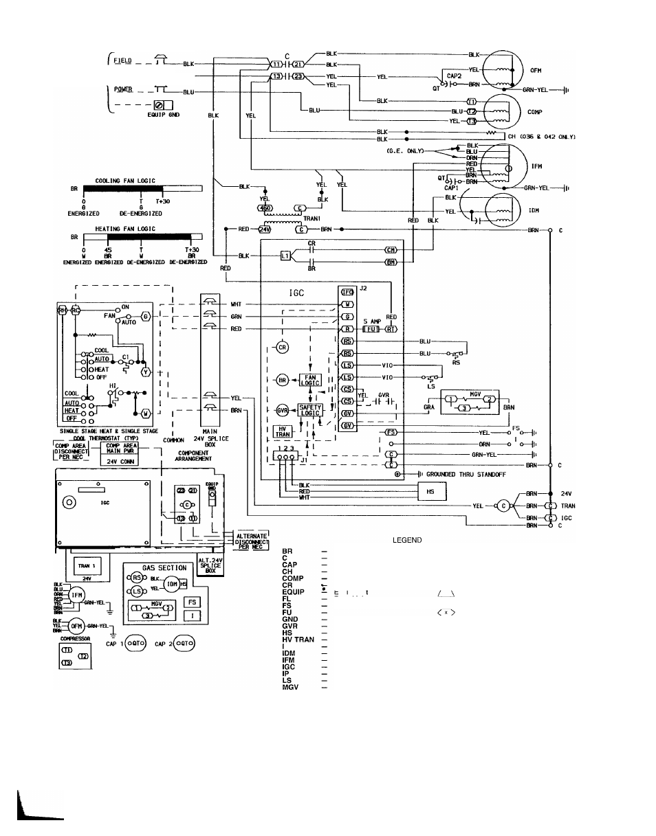
Blower Relay
Contactor
Capacitor
Crankcase Heater
Compressor Motor
Combustion Relay
Equipment
Fuse Link
Flame Sensor
Fuse
Ground
Gas Valve Relay
Hall Effect Sensor
High-Voltage Transformer
Ignitor
Induced-Draft Motor
Indoor-Fan Motor
Integrated Gas Control
Internal Protector
Limit Switch
Main Gas Valve
Outdoor-Fan Motor
Power
Quadruple Terminal
Rollout Switch
Transformer
Field Splice
Terminal (Marked)
Terminal (Unmarked)
Splice
Splice (Marked)
Factory Wiring
Field Control Wiring
Field Power Wiring
Accessory or Optional Wiring
To Indicate Common Potential
Only, Not to Represent Wiring
NOTES:
1 If any of the original wire furnished must be replaced, it must be replaced
with type 90 C wire or its equivalent
2 Thermostat: HH07AT174, HH01AD040, HH01AD046 Subbase: HH93AZ040,
HH93AZ176
3. Use copper conductors only
Fig. 27 — 460-3-60 Wiring Diagram, Units 48SS036-060
26