A warning – Carrier 48SX024-048 User Manual
Page 40
Attention! The text in this document has been recognized automatically. To view the original document, you can use the "Original mode".
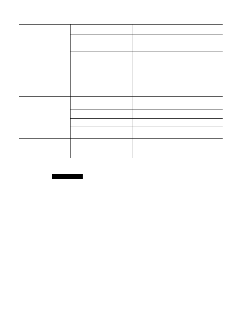
Table 15 — Heating Troubleshooting Chart
SYMPTOM
CAUSE
REMEDY
Burners will not ignite.
Water in gas line
Drain. Install drip leg.
No power to furnace
Check power supply fuses, wiring, or circuit breaker.
No 24-v power supply to control
circuit
Check transformer.
NOTE: Some transformers have internal overcurrent
protection that requires a cool-down period to reset.
Miswired or loose connections
Check all wiring and wirenut connections.
Burned-out heat anticipator in
thermostat
Replace thermostat.
Broken thermostat wire
Run continuity check. Replace wire if necessary.
Misaligned spark electrodes
Check flame ignition and sense electrode positioning.
Adjust as necessary.
No gas at main burners
1. Check gas line for air. Purge as necessary.
NOTE: After purging gas line of air, wait at least
5 minutes for any gas to dissipate before attempt
ing to light unit.
2. Check gas valve.
Inadequate heating.
Dirty air filter
Clean or replace filter as necessary.
Gas input to furnace too low
Check gas pressure at manifold. Match with that on
unit nameplate.
Unit undersized for application
Replace with proper unit or add additional unit.
Restricted airflow
Clean or replace filter. Remove any restriction.
Blower speed too low
Use faster speed tap if available, or install alternate
motor.
Limit switch cycles main burners
Check rotation of blower, thermostat heat antic
ipator settings, temperature rise of unit. Adjust as
necessary.
Poor flame characteristics.
Incomplete combustion results in:
Aldehyde odors, carbon monoxide,
sooting flame, floating flame
1. Tighten all screws around burner compartment.
2. Cracked heat exchanger. Replace.
3. Unit overfired. Reduce input (change orifices or
adjust gas line or manifold pressure).
4. Check burner alignment.
t
A
WARNING
Turn off the gas supply, then disconnect and tag elec
trical power to the unit before cleaning and lubricating
the blower motor and wheel. Failure to adhere to this
warning could cause personal injury or death.
To clean and lubricate the blower motor and wheel for
direct-drive models:
1. Remove and disassemble blower assembly as follows:
a. Remove blower access door.
b. Disconnect motor lead from blower relay (BR)
Disconnect yellow lead from terminal L2 of the
contactor.
c. Remove blower assembly from unit. Remove screws
securing blower to gas partition and slide assembly
out. Be careful not to tear insulation in blower
compartment.
d. Ensure proper reassembly by marking blower wheel
and motor in relation to blower housing before dis
assembly.
e. Loosen setscrew(s) that secures wheel to motor shaft,
remove screws that secure motor mount brackets to
housing, and slide motor and motor mount out of
housing.
2. Lubricate motor as follows:
a. Thoroughly clean all accumulations of dirt or grease
from motor housing.
b. Remove dust caps or plugs from oil ports located at
each end of motor.
c. Use a good grade of SAE 20 nondetergent motor oil
and put one teaspoon (Yie oz. or 16 to 25 drops) in
each oil port.
d. Allow time for oil to be absorbed by each bearing,
then wipe excess oil from motor housing.
e. Replace dust caps or plugs in oil ports.
3. Remove and clean blower wheel as follows:
a.
Ensure proper reassembly by marking wheel
orientation.
b. Lift wheel from housing. When handling and/or clean
ing blower wheel, be sure not to disturb balance weights
(clips) on blower wheel vanes.
c. Remove caked-on dirt from wheel and housing with
a brush. Remove lint and/or dirt accumulations from
wheel and housing with vacuum cleaner, using soft
brush attachment. Remove grease and oil with mild
solvent.
d. Reassemble wheel into housing.
e. Reassemble motor into housing. Be sure setscrews
are tightened on motor shaft flats and not on round
part of shaft.
f. Reinstall blower access door.
4. Restore electrical power, then gas supply to unit. Start
unit and check for proper blower rotation and motor speeds
during heating and cooling cycles.
t
40