Fig. 11 - slab mounting details, A caution, A warning – Carrier 48SX024-048 User Manual
Page 12: Warning
Attention! The text in this document has been recognized automatically. To view the original document, you can use the "Original mode".
2 0
'1
FLUSH WITH SLAB-
■ ^ -I
T___ ^
J
r
2
0
”
12 0”
CONCRETE SU\B-
Fig. 11 - Slab Mounting Details
SECURE SCREW
AGAINST BASEPAN
TO HOLD LIFTING
BRACKET IN PLACE
DETAIL A
Hook rigging shackles through holes in lifting brackets, as shown in
Detail “A.” Lifting brackets to be centered around the unit center of
gravity Use wooden top skid when rigging, to prevent rigging straps
from damaging unit
A CAUTION
All panels must be in place when rigging.
UNIT
48SS
MAX
WEIGHT
A
B
C
Size
lb
kg
in.
mm
in.
mm
in.
mm
018
332
150
24.3
618
24 85
631
024
375
170
22 4
570
24.85
631
030
384
174
22.3
565
24 85
631
036
408
185
49 4
1255
22.0
559
24.85
631
042
447
203
22.5
570.7
28.85
733
048
486
220
21.0
533
34.85
885
060
525
238
21.5
545
34.85
885
UNIT
48SX
024
405
184
22 8
579
28.9
733
030
408
185
22 4
569
28.9
733
036
438
199
40.4
1255
22.4
569
28.9
733
042
463
210
22.8
579
34.9
885
048
494
224
21.1
536
34.9
885
Hook rigging shackles through holes in lifting brackets, as shown in
Detail “A ” Lifting brackets to be centered around the unit center of
gravity. Use wood top skid when rigging, to prevent rigging straps
from damaging unit. Remove 4 screws to slide wood support through
rectangular hole in rail
A CAUTION
All panels must be in place when rigging.
UNIT
48SS
MAX
WEIGHT
A
B
C
Size
lb
kg
in.
mm
in.
mm
in.
mm
018
320
145
24.4
619
28.2
715
024
363
165
22.6
574
28.2
715
030
380
172
22.5
571
28.2
715
036
396
180
49 4
1255
22.2
563
28.2
715
042
435
197
22.6
574
32.2
816
048
474
215
21.2
538
38.2
969
060
513
233
21.6
549
38.2
969
UNIT
48SX
024
393
178
22.9
582
32.2
816
030
396
180
22.6
574
32.2
816
036
426
193
49 4
1255
22.5
571
32.2
816
042
451
205
22.9
582
38.2
969
048
482
219
21.3
540
38.2
969
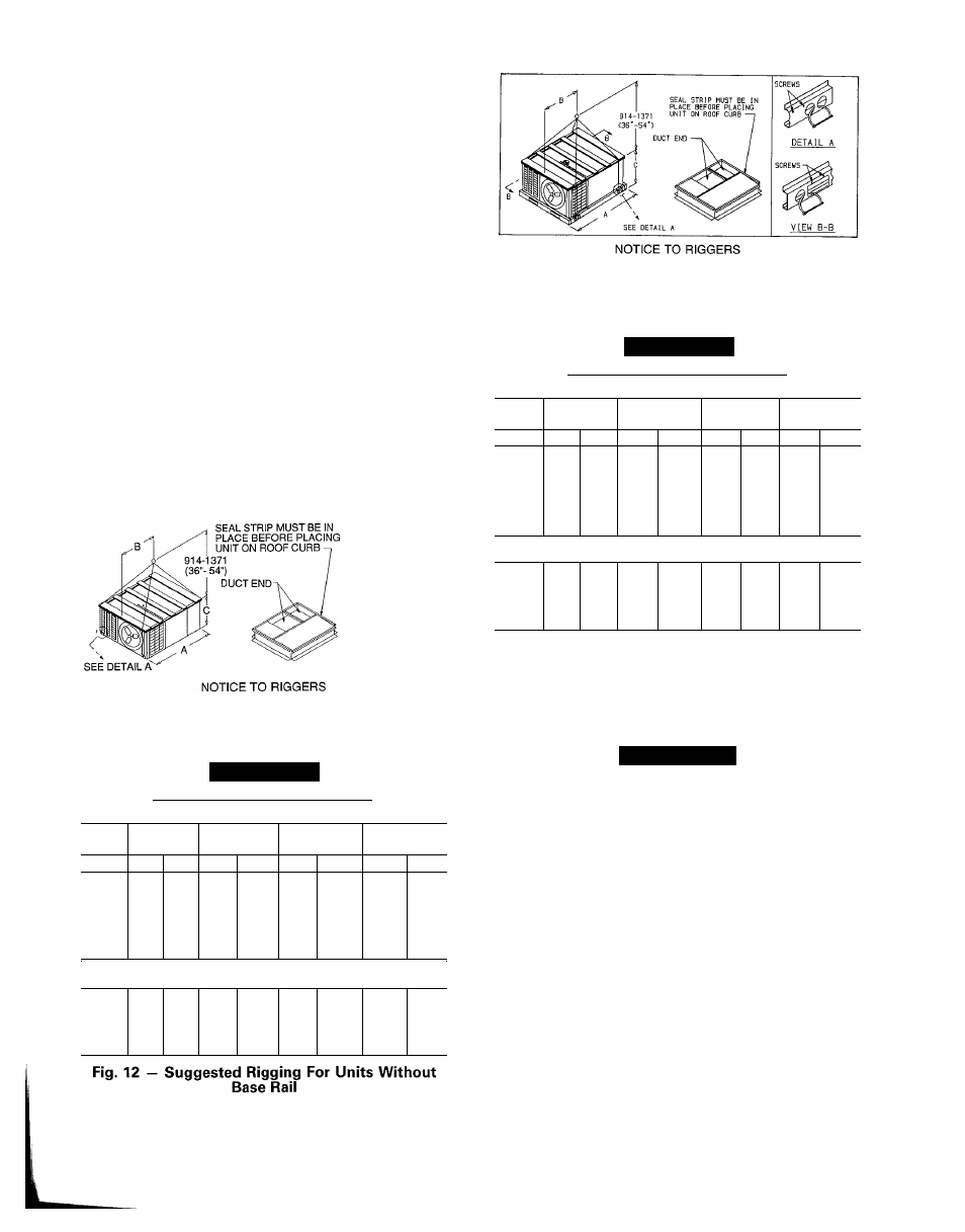
Fig. 13 - Suggested Rigging For Units With
Optional Base Rail
UNITS WITHOUT BASE RAIL - If accessory rigging
brackets are to be used for rigging, install them as follows:
A
WARNING
Secure screws and paint protectors solidly against unit
basepan to hold lifting brackets in position.
Never use lifting brackets when the temperature is be
low -10 F.
Never exceed 200 lbs per bracket of lifting force.
Never use lifting brackets for lifting other models of
air-conditioning units.
Lifting point should be directly over the unit center of
gravity.
1. Position brackets as close to the corners of unit as pos
sible. Be sure brackets are well outside of center of grav
ity. (See Fig. 2, 4, 6, 8, and 12.).
2. Position paint protectors and foam strips between screws
and painted surface of unit. Tighten screws until they
make contact with the paint protectors.
3. Secure device or hook of sufficient strength to hole in
bracket as shown in detail “A” of Fig. 12.
4. If wood top is available, use it for a spreader bar to pre
vent straps from damaging unit. If wood top is not avail
able, use spreader bars of sufficient length.
12