Carrier 48SX024-048 User Manual
Page 4
Attention! The text in this document has been recognized automatically. To view the original document, you can use the "Original mode".
o 7/8 (22.23)
ALTERNATE LV ENTRY
1 1/4 (31.75)
ALTERNATE POWER ENTRY
1 13/16'
(46.2)
OPTIONAL SUPPLY
AIR OPENING
-4 3/4'
(120
6
)
i
12l5/1
215/16
(312.7)
BLOWER ACCESS -
PANEL
RIGHT SIDE VIEW
BURNER AND CONTROL BOX
ACCESS PANEL
5/8 -
(16 S)
COMPRESSOR ACCESS PANEL
y-2 3/16' ^3/4' NPT (19.0)
(55 6)
DRAIN OUTLET
FRONT VIEW
t
. . 0
36 (914)
36 (914)
36 (914)
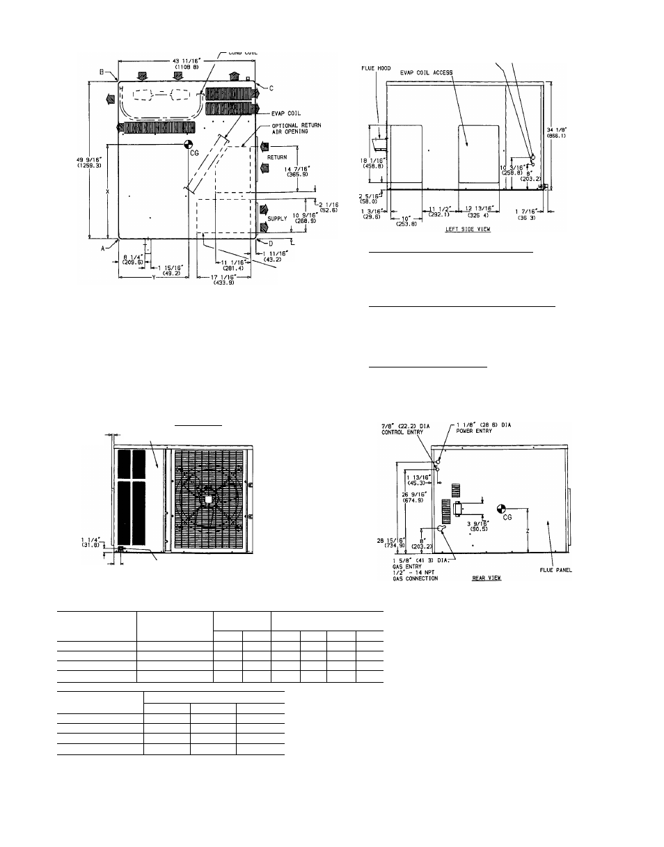
REQ’D CLEARANCES FOR SERVICING, in. (mm)
Duct panel
. .
Unit top .
Side opposite ducts
Compressor access
(Except for NEC requirements)
REQ’D CLEARANCES TO COMBUSTIBLE MAIL in (mm)
Maximum extension of overhangs
. .
48(1219)
Unit top. ...
...
14(356)
Duct side of unit ...
.0
Side opposite ducts
.
.
.
.
9 (229)
Bottom of unit
...................... . . 0
Flue panel
30 (762)
NEC REQ’D CLEARANCES in (mm)
Between units, control box side
.42(1067)
Unit and ungrounded surfaces, control box side . .
36(914)
Unit and block or concrete walls and other grounded
surfaces, control box side
. .
.
...
42 (1067)
UNIT
ELECTRICAL
CHARACTERISTICS
UNIT WEIGHT
CORNER WEIGHT
(Ib/kg)
lb
kg
A
B
C
D
48SS048080
208/230-1-60
414
188
107/49
83/38
158/72
66/30
48SS048100/120/140
208/230-1-60
426
193
110/50
86/39
159/72
71/32
48SS060080
208/230-1-60
453
206
117/53
93/42
167/76
76/35
48SS060100/120/140
208/230-1-60
465
211
120/55 96/44
167/76
82/37
UNIT
CENTER OF GRAVITY (In./mm)
X
Y
Z
48SS048080
28 76/731
23 46/596
15 35/390
48SS048100/120/140
28.42/722
23.42/595
15.35/390
48SS060080
28.36/720
23 27/591
15.35/390
48SS060100/120/140
27 95/710
23 23/590
15 35/390
LEGEND
CG
— Center of Gravity
MAT’L
COND
— Condenser
NEC
LV
— Low Voltage
REQ'D
— Material
— National Electrical Code
— Required
NOTE: Clearances must be maintained to prevent recirculation of
air from outdoor-fan discharge.
Fig. 4 — 4888048,060 Without Base Rail, Unit Dimensions