A warning, Led indications – Carrier 48SX024-048 User Manual
Page 23
Attention! The text in this document has been recognized automatically. To view the original document, you can use the "Original mode".
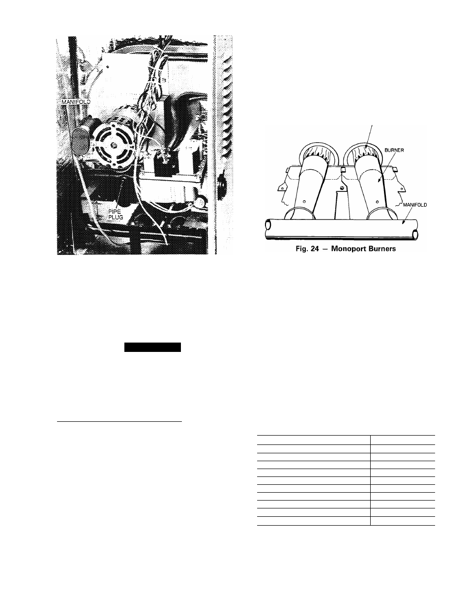
Fig. 23 — Burner Assembly
Observe manifold pressure and proceed as follows to ad
just gas input:
1. Remove cover screw over regulator adjustment screw
on gas valve.
2. Turn regulator adjustment screw clockwise to increase
gas input, or turn regulator adjustment screw counter
clockwise to decrease input. Manifold pressure must be
between 3.4 and 3.6 in. wg.
A
WARNING
Unsafe operation of the unit may result if manifold
pressure is outside this range. Personal injury or unit
damage may result.
3. Replace cover screw cap on gas valve.
4. Turn off gas supply to unit. Remove manometer from
pressure tap and replace pipe plug on gas valve. Turn on
gas to unit and check for leaks.
Measure Manifold Pressure (Propane Units') — The main
burner orifices on a propane gas unit are sized for the unit
rated input when the manifold pressure is 3.5 in. wg.
Proceed as follows to adjust gas input on a propane gas
unit:
1. Turn off gas to unit.
2. Remove pipe plug on manifold (see Fig. 23), then con
nect manometer at this point.
3. Turn on gas to unit.
4. Remove cover screw over regulator adjustment screw
on gas valve.
5. Adjust regulator adjustment screw for a manifold pres
sure reading of 3.5 in. wg. Turn adjusting screw clock
wise to increase manifold pressure, or turn adjusting screw
counterclockwise to decrease manifold pressure.
6. Replace cover screw.
7. Turn off gas to unit. Remove manometer from pressure
tap. Replace pipe plug on gas valve, then turn on gas to
unit. Check for leaks.
CHECK BURNER ELAME - With burner access panel
removed, observe the unit heating operation. Watch the burner
flames to see if they are light blue and soft in appearance,
and that the flames are approximately the same for each
burner. See Fig. 24. Refer to Maintenance section for in
formation on burner removal.
AIRFLOW AND TEMPERATURE RISE - The heating
section for each size unit is designed and approved for heat
ing operation within the temperature-rise range stamped on
the unit rating plate.
BURNER FLAME
Table 6 shows the approved temperature-rise range for
each heating input, and the air delivery cfm at various tem
perature rises The heating operation airflow must produce
a temperature rise that falls within the approved range.
Refer to Maintenance section on page 39 to adjust heat
ing airflow when required.
HEATING SEQUENCE OF OPERATION - See Fig. 25-30
and unit wiring label.
On a call for heating, terminal “W” of the thermostat is
energized, starting the induced-draft motor. When the hall-
effect sensor on the induced-draft motor senses that it has
reached the required speed, the burner sequence begins. The
indoor-fan motor is energized 45 seconds after flame is
established. When the thermostat is satisfied and “W” is
deenergized, the burners stop firing and the indoor-fan mo
tor shuts off after a 45-second time-off delay.
A LED (light-emitting diode) indicator is provided on the
control board to monitor operation. The control board is lo
cated by removing the burner access panel. During normal
operation, the LED is continuously on. See chart below for
error codes:
LED Indications
ERROR CODE
LED INDICATION
Normal Operation
On
Hardware Failure
Off
Fan On/Off Delay Modified
1 Flash
Limit Switch Fault
2 Flashes
Flame Sense Fault
3 Flashes
Five Consecutive Limit Switch Faults
4 Flashes
Ignition Lockout Fault
5 Flashes
Inducer Switch Fault
6 Flashes
Rollout Switch Fault
7 Flashes
Internal Control Fault
8 Flashes
NOTES:
1 There is a 3-second pause between error code displays.
2 If more than one error code exists, all applicable error codes will
be displayed in numerical sequence
3 This chart is on the wiring diagram located inside the burner ac
cess panel.
23