Fig. 21 — high- and control-voltage connections, A warning – Carrier 48SX024-048 User Manual
Page 19
Attention! The text in this document has been recognized automatically. To view the original document, you can use the "Original mode".
THERMOSTAT (TYPICAL)
(^(
y
)(^(R)0
LEADS (SEE UNIT
WIRING LABEL)
LEGEND
--------- Field Control-Voltage Wiring
------- — Field High-Voltage Wiring
NOTE: Use biue wire for 3-phase units only
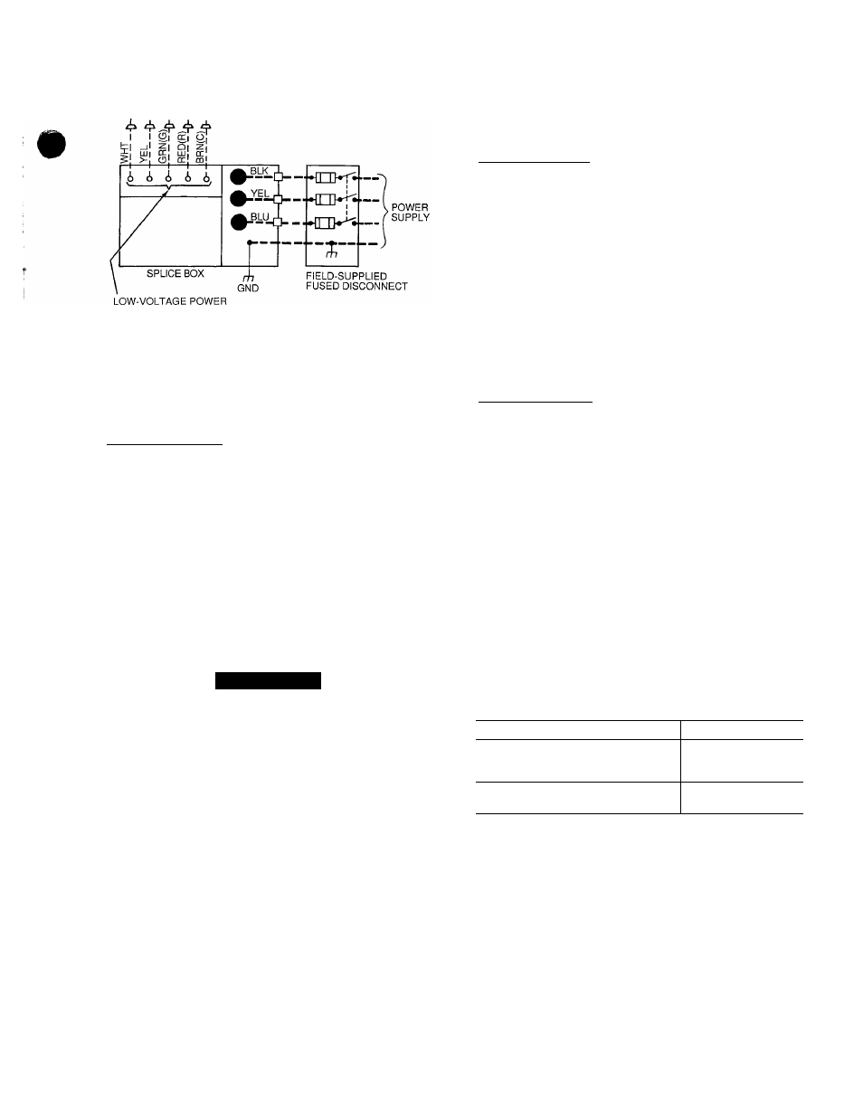
Fig. 21 — High- and Control-Voltage Connections
Alternate Power Entry
6
.
Remove knockouts in fixed compressor panel located on
duct panel side of unit.
Route high-voltage leads into high-voltage terminal box.
Connect ground wire to green-yellow wire using field-
supplied splice.
Connect power wires to unit high-voltage leads.
On 3-phase units, locate blue wire projecting from com
pressor junction box. Cut wire at partition and route into
high-voltage junction box through grommet in back of
junction box.
On 3-phase units, strip back blue lead and connect to
third leg of the power wires.
SPECIAL PROCEDURES FOR 208-V OPERATION
A
WARNING
Make sure that the gas supply then the power supply to
the unit is switched OFF before making any wiring
changes. Electrical shock can cause personal injury or
death.
6
.
Disconnect the orange transformer-primary lead from the
contactor. See unit wiring label.
Remove the tape and wirenut from the terminal on the
end of the red transformer-primary lead.
Save the wirenut.
Connect the red lead to the contactor terminal from which
the orange lead was disconnected.
Using the wirenut removed from the red lead, insulate
the loose terminal on the orange lead.
Wrap the cover with electrical tape so that the metal ter
minal cannot be seen.
CONTROL VOLTAGE CONNECTIONS - Locate the room
thermostat on an inside wall in the space to be conditioned,
where it will not be subjected to either a cooling or heating
source or direct exposure to sunlight. Mount the thermostat
4 to 5 ft above the floor
NOTE. Do not use any type of power-stealing thermostat.
Unit control problems may result.
Use no. 18 American Wire Gage (AWG) color-coded,
insulated (35 C minimum) wires to make the control volt
age connections between the thermostat and the unit. If the
thermostat is located more than 100 ft from the unit (as
measured along the control voltage wires), use no. 16 AWG
color-coded, insulated (35 C minimum) wires.
Standard Connection — A grommeted, control-voltage in
let hole is located in the flue panel adjacent to the control
access panel. See Fig 2-9. Provide a drip loop before run
ning wire through panel.
Run the low-voltage leads from the thermostat, through
the inlet hole, and into unit low-voltage splice box.
Locate five 18-gage wires leaving control box. These low-
voltage connection leads can be identified by the colors red,
green, yellow, brown, and white). (See Fig. 21.) Cut wires
at the point where they exit control box. On 48SX024,030,
do not cut yellow wire. Stripped yellow lead is located in
connection box. Ensure the leads are long enough to be routed
into the low-voltage splice box located below the right side
of the control box. Route leads through hole in bottom of
control box and make low-voltage connections as shown in
Fig. 21. Secure all cut wires, so that they do not interfere
with operation of unit.
Alternate Connection — Remove knockout in compressor
fixed panel located below high-voltage knockout. Remove
rubber grommet from standard low-voltage power entry and
install it in hole left when knockout was removed. Route
thermostat wires through grommet providing drip loop at
panel Connect low-voltage leads as shown in Fig. 21. On
48SX024 and 030 units, the yellow wire originating from
discharge thermostat of compressor must be cut and routed
into low-voltage section of junction box.
HEAT ANTICIPATOR SETTING - The room thermostat
heat anticipator must be properly adjusted to ensure proper
heating performance. Set the heat anticipator, using an am
meter between the W and R terminals to determine the
exact required setting.
NOTE: For thermostat selection purposes, use 0.18 amp
for the approximate required setting.
Failure to make a proper heat anticipator adjustment will
result in improper operation, discomfort to the occupants
of the conditioned space, and inefficient energy utilization;
however, the required setting may be changed slightly
to provide a greater degree of comfort for a particular
installation.
Recommended thermostats are as follows:
TYPE
PART NO.
Single-Stage Heating and
Cooling Manual Changeover
HH01AD040*
HH01AD046
HH01PC184
Auto. Changeover
HH07AT174t
HH01PC185
19
•Recommended for use with subbase HH93AZ040
tRecommended for use with subbase HH93AZ176
TRANSFORMER PROTECTION - The unit transformer
protection may be one of 2 types.
The first transformer type may contain an auto, reset over
current protector for control circuit protection. If this de
vice trips, it may reset without warning, starting the heat
ing or cooling section of this product. Use caution when
servicing; if overcurrent protector continues to trip, there is
a problem in the low-voltage electrical circuit, such as an
electrical short, ground, or transformer overload. Discon
nect power, correct the condition, and check for normal unit
operation.
The second transformer type is of the energy-limiting type.
It is set to withstand a 30-second overload or shorted
secondary condition.