Carrier 48SX024-048 User Manual
Page 17
Attention! The text in this document has been recognized automatically. To view the original document, you can use the "Original mode".
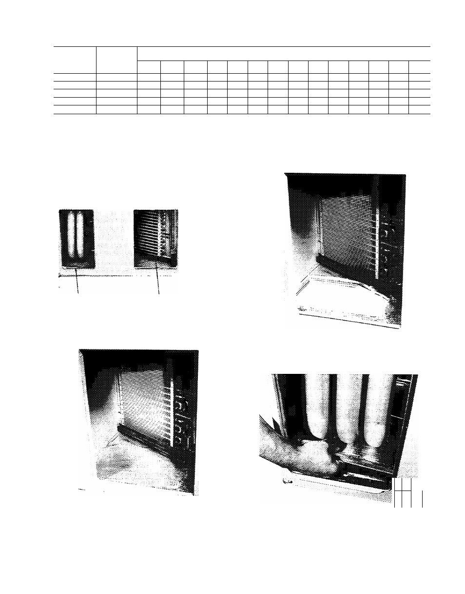
Table 3 — Maximum Gas Flow Capacity*
NOMINAL
IRON PIPE,
SIZE
(In.)
INTERNAL
DIAMETER
(In.)
LENGTH OF PIPE, FTf
10
20
30
40
50
60
70
80
90
100
125
150
175
200
V2
.622
175
120
97
82
73
66
61
57
53
50
44
40
—
—
%
.824
360
250
200
170
151
138
125
118
110
103
93
84
77
72
1
1 049
680
465
375
320
285
260
240
220
205
195
175
160
145
135
1V4
1.380
1400
950
770
600
580
530
490
460
430
400
360
325
300
280
IV
2
1.610
2100
1460
1180
990
900
810
750
690
650
620
550
500
460
430
‘Capacity of pipe in cu ft of gas per hr for gas pressure of 0.5 psig or iess. Pressure drop of 0 5-in. wg
(based on a 0.60 specific gravity gas). Ref: Tabie C-4, Nationai Fire Protection Association NFPA54.
fThis iength inciudes an ordinary number of fittings.
SUPPLY DUCT
OPENiNG
RETURN DUCT
OPENiNG
Fig. 16 — Supply and Return Duct Openings
Fig. 18 — Vertical Duct Cover Removed
M.
Fig. 17 - Lance Location for Vertical Duct
Opening Cover
Fig. 19 — Removal of Vertical Discharge
Opening Cover
17