9 communication, 1 overview, 2 hardware interface – YSI 6000UPG User Manual
Page 129: Communication
9-1
9. COMMUNICATION
This section describes the communications protocol that the 6000
UPG
uses to communicate with the
host system. Section 1 gives a brief overview of the communication ability of the 6000
UPG
. The
remaining sections describe available hardware and software features.
9.1 OVERVIEW
The 6000
UPG
communicates via a serial port that can be configured as either SDI-12 or as a 3 wire
RS-232 interface. The serial port supports the following configurations:
Baud rate:
300, 600, 1200, 2400, 4800, 9600, 19200
Data Bit:
7,8
Parity:
None
Handshake:
XON/XOFF
Interface:
RS-232, SDI-12, Modem
Default:
RS-232
With these configurations, the 6000
UPG
is capable of interfacing to a variety of devices from a
“dumb” terminal to numerous data collection platforms.
With the built-in non-volatile memory, the 6000
UPG
can store from several weeks to several months
of data depending on the logging interval. Data can be retrieved using the ASCII or the more
sophisticated Kermit file transfer protocol (FTP). The advantage of the Kermit FTP is its capability
for error detection and retransmitting.
9.2 HARDWARE INTERFACE
Connection from the Model 6000
UPG
to the host computer is provided using the YSI 6095 MS-8 to
DB-9 female adapter. This 6095 then connects to the standard DB-9 male connector on the host
computer. The Model 6000
UPG
PC interface cable is wired for direct connection to a DTE device.
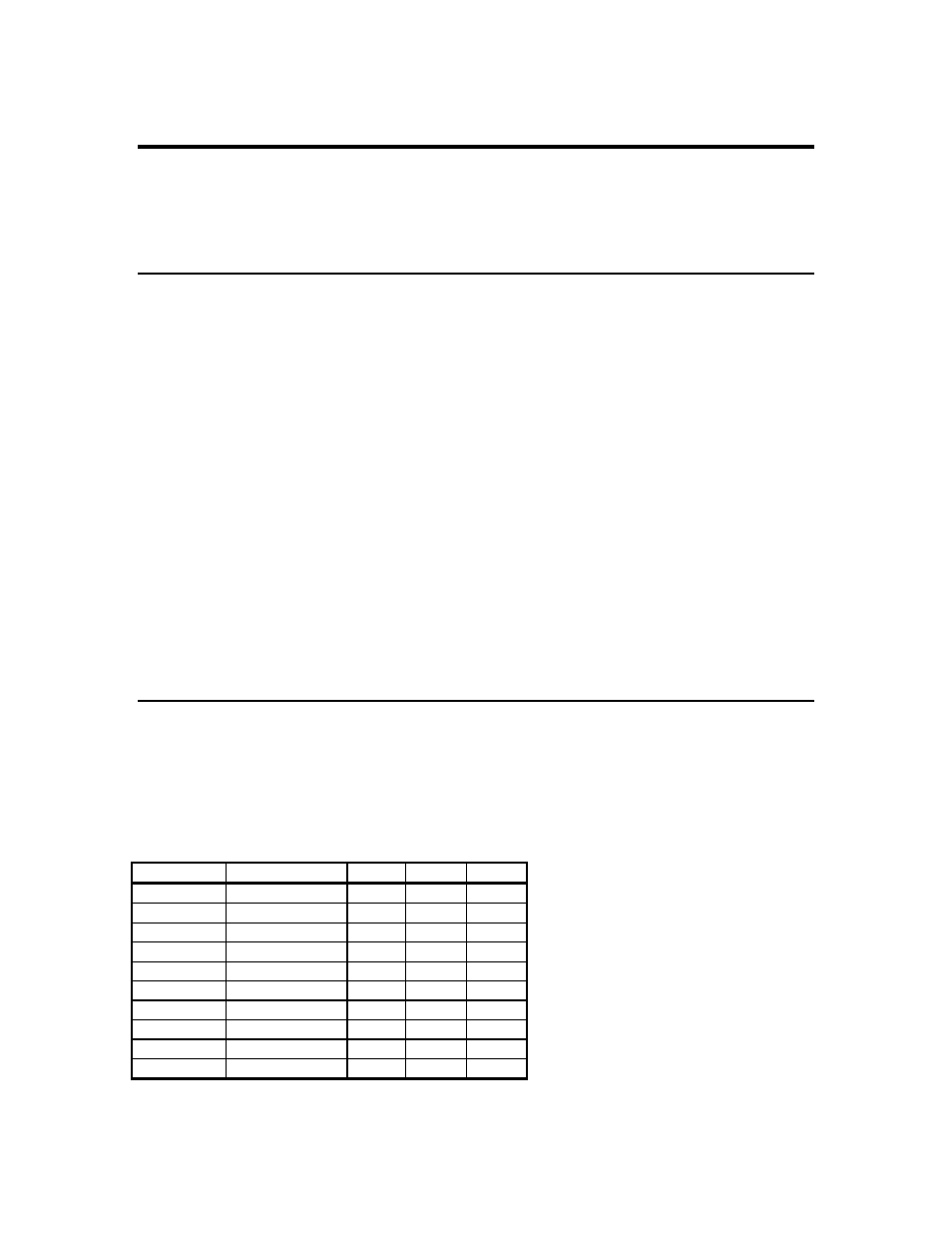
The following table defines the interface circuits. The signals and their directions are defined with
respect to use of the Model 6000
UPG
with the 6095 adapter.
Wire Color
Pin Description
DB-9
MS-4
MS-8
Yellow
RS232 TX
2
----
C
Orange
RS232 RX
3
----
D
Green
Alarm
----
----
E
Gray
RTS
----
----
G
Blue
CTS
----
----
H
Red
+ 12V DC
9
A
A
Black
GND
5
C
B
Purple
SDI-12
----
B
F
Bare
Shield
----
----
B