Get ready to build – Top Flite TOPA0120 User Manual
Page 8
The most serious deviation is in the rear
portion of the canopy. The rear window recesses
(White ABS plastic in the model kit) were removed
from the full scale aircraft. This is presumably to
allow for a passenger. If you plan to enter serious
competition, you will probably want to modify your
kit to eliminate these panels. We chose to have
the kit build as a stock P-40E.
The P-40 was equipped with a variety of guns.
The guns in the photos differ from the ones on the
3-view. This is not a problem; just duplicate the
ones in the photos as we did on our prototypes
using 3/16” brass tubes.
Always work from the photos of the full size
aircraft and the proper 3-view drawing when
finishing your model because that is what you will
use for documentation.
SCALE RETRACTS AND DOORS
The retract landing gear pivot location shown
on the plans is correct. The stance of the model
(and strut length) shown with the gear down is
correct. Keep in mind that the Warhawk's gear,
like that in most modern aircraft, compresses
under the weight of the aircraft and extends when
the aircraft takes off. This fact means that the rigid
struts commonly used on models will not fold into
the scale locations. The normal way to deal with
this problem in models is to set up the model to
have the proper stance, and then have the wheel
retract into a position short of the scale location.
The only other reasonable way to overcome this
problem is to use oleo struts (such as Robart
Robostruts) that have springs light enough to
compress under the weight of the model and thus
function in a scale fashion.
The full scale P-40 uses landing gear doors on
the pods. We have not made these functional on
any of our models so we cannot offer any help on
implementing these.
GET READY TO BUILD
NOTE: When you see "CA," use super
thin Supreme glue. When you see
"CA+," use thick Supreme glue.
❑
1. Unroll the plan sheets. Re-roll the plans
inside out to make them lie flat.
❑
2. Remove all parts from the box. As you do,
identify the name of each part by comparing it with
the plans and the parts list at the back of this book.
Using a felt tip or ball point pen, write the part
name or size on each piece to avoid confusion
later. Use the die-cut patterns shown on pages 4
and 5 to identify the die-cut parts and mark them
before punching out. Save all scraps. If any of
the die-cut parts are difficult to punch out, do not
force them! Instead, first cut around the parts with
a sharp hobby knife. After punching out the die-cut
parts, use your T-Bar or sanding block to lightly
sand the edges to remove any die-cutting
irregularities.
❑
3. As you identify and mark the parts, separate
them into groups, such as fuse (fuselage), wing,
fin and stab (stabilizer), and hardware.
BUILD THE HORIZONTAL STABILIZER
❑
1. Work on a flat surface over the plans
covered with waxed paper. Refer to the plans to
identify the parts and their locations.
❑
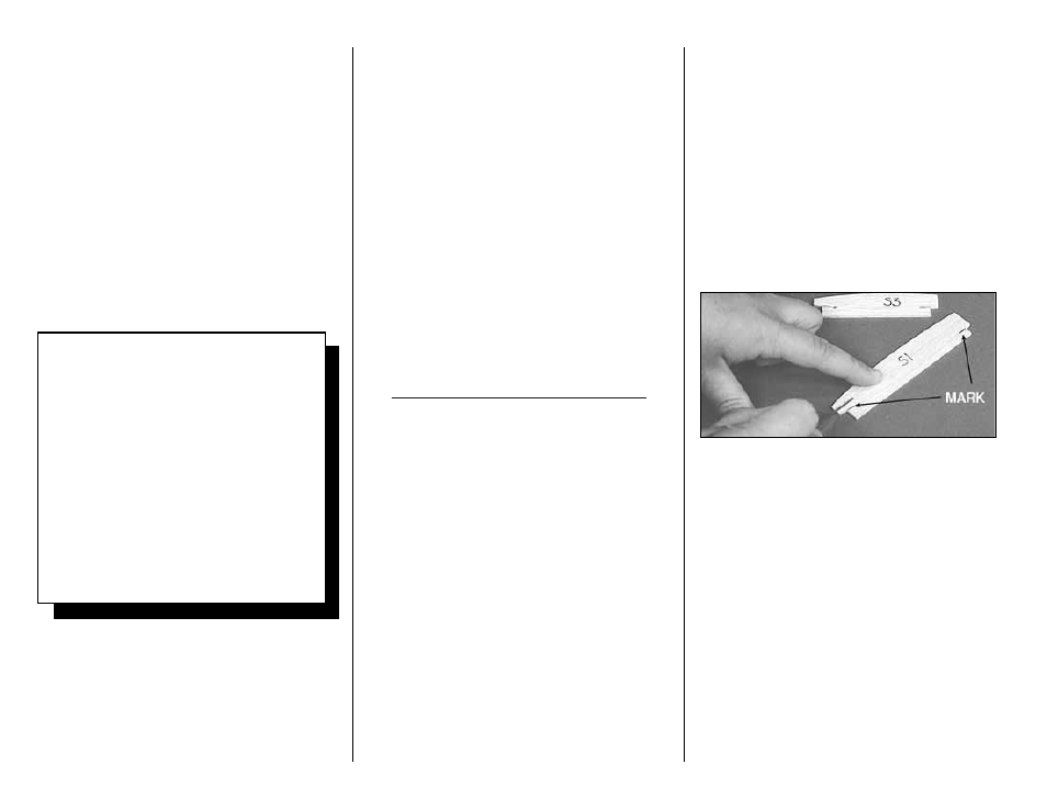
2. Punch out both sets of the die-cut 3/32”
balsa ribs S-1 to S-6. There is a jig tab on the
bottom edge of each of these ribs. If any of these
break off, carefully glue them back on with CA.
Lightly sand any imperfections. You may need to
finish cutting the notch in the forward portion of S-1
for the Stab Joiner (SJ) with a knife. Use a pen to
mark the extensions of the bottom edge of the ribs
across the fore and aft ends of the jig tabs. These
will help you when you trim off the jig tabs later.
❑
3. The stab Trailing Edges (S) are die-cut
from 1/4” balsa. Since some crushing may happen
when die-cutting wood of this thickness, they are
supplied slightly long and can be trimmed. True up
the ends of these pieces with sandpaper. Also
true up the top and bottom edges of these pieces
with a T-bar.
- 8 -
SCALE DOCUMENTATION
This model was designed using the Koku-Fan
3-view drawings as the reference for outline.
This fact makes it preferable to use those
drawings for scale documentation. The
drawings and many Warhawk photo packs are
available from:
Scale Model Research
3114 Yukon Ave
Costa Mesa, CA 92626
(714) 979-8058
The trim scheme shown on the box is from
photo pack #588 (54 pictures $35) -or- #588a
(16 pictures $16) +$3 S&H