Top Flite TOPA0120 User Manual
Page 23
❑ ❑
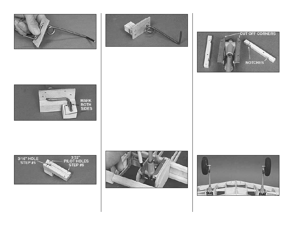
3. Test fit the bent Landing Gear wire
through the Landing Gear Plate. Chamfer the hole
in the plate for the wire, if required, until the wire
will lie fairly flat on the plate.
❑ ❑
4. Hold the Landing Gear Rail assembly
up to the Landing Gear Plate and wire. Mark the
location where the wire will insert into the Landing
Gear Rail.
❑ ❑
5. Drill the Landing Gear Rail assembly
with a 3/16” drill. Test fit the parts together and
chamfer the hole entries as required for a good fit.
Note: Small gaps will be pulled together when the
parts are screwed together.
❑ ❑
6. Mark the locations for the #4 screws.
Drill 3/32” pilot holes at the locations you marked.
Screw the parts together with #4 x 1/2” Sheet
Metal Screws.
MOUNT THE LANDING GEAR
Do the following eight steps for Retract and
Fixed Gear.
If you are using fixed gear, just substitute the fixed
gear assemblies for the retracts. They mount the
same way.
NOTE: By mounting the retracts to the rails first,
then gluing the rails into the structure, the retract
frames will be relaxed. If you glue the rails in by
themselves, the frame is likely to be bent when you
tighten the mounting screws; this will cause the
retracts to bind.
❑ ❑
1. Fit the 1/4 x 5/16” x 3-1/8” Landing
Gear Rails and the retracts between ribs W-3 and
W-4 as shown in the picture. Mark the locations of
the retract (or fixed gear) mounting screws.
❑ ❑
2. Remove the Rails and drill the locations
you marked with a 7/64” bit.
❑ ❑
3. Mark the locations of any notches you
need to make in the rails to facilitate retract
removal. Make these notches with a Dremel
®
Moto-Tool
®
.
NOTICE how the front corners of the
retract mounting lugs have been cut off
at an angle. This provides more
clearance for the landing gear pods.
The corners may be cut off using a
cutoff wheel. Be sure to use safety
glasses when using a cutoff wheel.
❑
4. Mount the retracts (or fixed gear
assemblies) to the rails with #6 x 1/2” sheet metal
screws.
❑
5. Test fit both retracts with rails into the wing
structure. View the struts from all angles to check
- 23 -