Top Flite TOPA0120 User Manual
Page 22
Place the 3/8” x 2-5/8” x 10” balsa Wing Jig Block
under W-1. The W-1 jig tabs and the spar at W-1
should contact the Wing Jig Block. The W-12 jig
tabs and the spar at W-12 should contact your flat
work table.
❑
8. When you have confirmed that all of the
parts fit well, disassemble the wing parts. Coat the
inside of the Dihedral braces and the area of the
Spars that they contact with a thin film of 30-minute
epoxy. Reassemble the wing parts onto the jig
block. Align the two W-1 ribs with each other and
glue them together with CA. Make sure the wing is
properly jigged. Clamp the Dihedral braces to the
Spars with clamps or masking tape.
❑
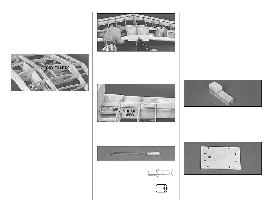
9. Apply a fillet of 30-minute epoxy around the
Wing Bolt Plate.
❑
10. Use 30-minute epoxy to fill any gaps
where the Spars join in the middle.
❑
11. Drill a 3/16” pilot hole through the wing LE
for the 5/16" Wing Dowel. Gradually enlarge the
hole to 5/16” keeping the drill centered on the two
W-1 ribs.
❑
12. Make a 1/16” balsa shear web to fit
between W-2 and W-3. Glue it to the Dihedral
Brace on the aft side of the spar.
❑
13. Make the aileron pushrods from the 4”
threaded end rod. Use a Nylon
Clevis with a Clevis Retainer on
the horn end and a Z-bend on
the Bellcrank end. Make them
the length shown on the wing
plan top view.
❑
14. Drill out the outer hole in the bellcranks
with a 5/64” drill bit. Test fit the pushrod into the
bellcrank.
FIXED LANDING GEAR ASSEMBLY
Do the following six steps to make a left and a
right fixed gear assembly.
NOTE: The fixed gear is slightly shorter
than scale to improve ground handling.
❑ ❑
1. Use 30-minute epoxy to glue the 3/4” x
5/8” x 1” hardwood Landing Gear Block to one
end of the slotted 1/2” x 3/4” x 2-3/4” hardwood
Landing Gear Rail as shown on the plan and in
the photo.
❑ ❑
2. Locate the 1/8” x 1-11/16” x 2-3/4” birch
plywood Landing Gear Plate. Use the template
provided on the wing plan to mark the hole
locations. Drill the holes to the sizes indicated on
the template.
- 22 -