Top Flite TOPA0120 User Manual
Page 32
❑
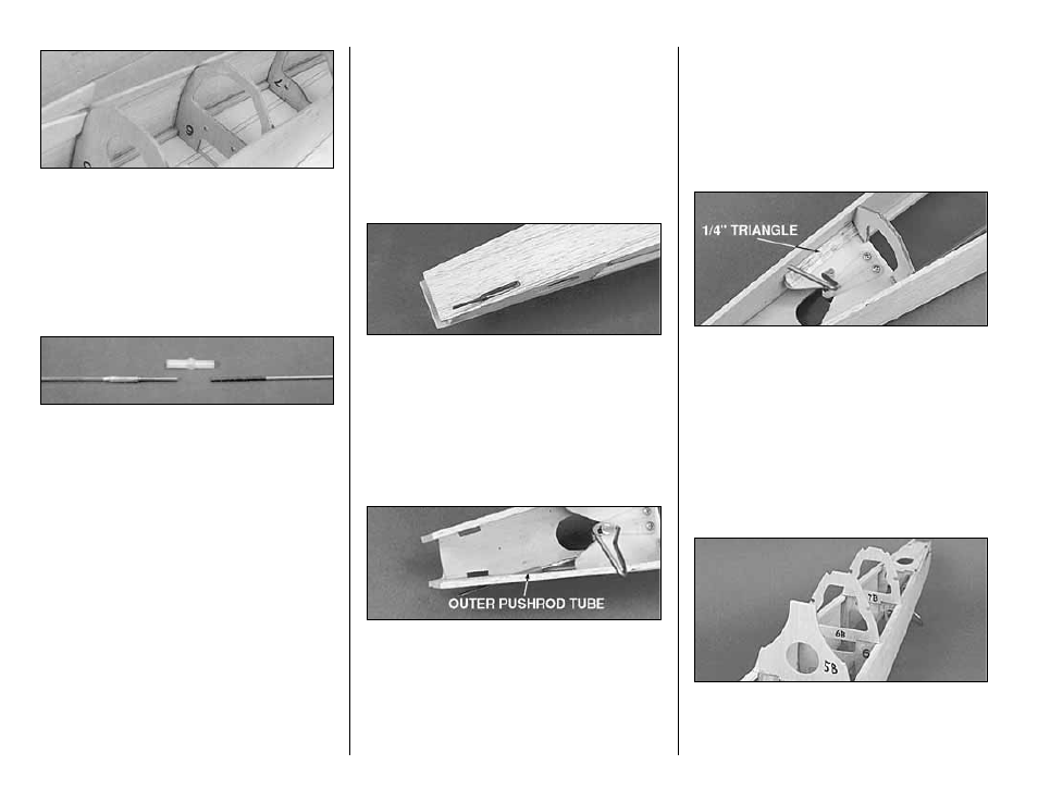
26. Glue in Formers F-5, F-6, and F-7 at the
locations marked on the plans. Make sure the
formers are perpendicular to the building board.
Pull the fuselage sides together at the aft end, and
glue them to F-8 and the Stab Support Crutch.
❑
27. Cut 3” off one end of the .074 x 35”
Threaded Both End Rod. Place a brass
Threaded Coupler over the unthreaded end of the
3” piece. Measure the length of the assembly. Cut
off the wire until the total assembled length is
3-1/2”. Silver solder the brass coupler to the wire.
❑
28. Screw the threaded end of the remaining
32” rod well into the end of the Nylon Two-Ended
Ball Link Socket.
❑
29. Cut outer Pushrod Tube for rudder to the
length shown on the plans and slide it through
formers F-8, F-7, F-6, F-5 and F-4. The Rudder
outer pushrod tube protrudes through former F-4
approximately 3/4” and through former F-8
approximately 3/8”. Roughen the outer pushrod
tube at the formers so the adhesive will stick. Glue
the pushrod tube in place with CA+.
❑
30. Slide 5/16” lengths of Inner Pushrod
Tube over the 32” pushrod wire. Space them
approximately 2” apart. See the side view of the
plans for proper spacings.
❑
31. Insert the pushrod wire into the rudder
outer tube and snap the ball link on the tail wheel
steering arm.
❑
32. Mark and cut out the rudder pushrod exit
where shown on the fuselage plans. Bevel the exit
with a sharp knife at the front from the inside and
at the back from the outside.
NOTE: A Molded Hooded Pushrod Exit
may be used instead of the outer
Pushrod tube.
❑
33. Cut a 1-1/4” piece of outer Pushrod Tube
from the tubing supplied in the kit. Slide the tube
into the pushrod exit slot through the fuselage side.
Approximately 1/4" of the tube should be inside the
fuselage. Trim the Pushrod Tube flush with the
outside surface of the fuselage side. Glue the
Pushrod Tube securely in place with CA+.
❑
34. Screw the 3-1/2” piece of pushrod into the
open end of the Nylon Ball Link. Position the brass
coupler end so that it is inside the fuselage. Check
the plans for the proper bend in the pushrod and
bend to match.
❑
35. Cut two 2” lengths of 1/4” balsa Triangle
Stock and glue them in place to reinforce the joints
of TW and the fuselage sides.
❑
36. Check all of the fuselage glue joints and
re-glue any weak joints at this time.
BUILDING THE FUSELAGE TOP
❑
1. Glue the die-cut 1/8” Former Tops F-5B, F-
6B and F-7B to the tops of their respective
formers.
- 32 -