Top Flite TOPA0120 User Manual
Page 13
❑ ❑
2. Draw a centerline on both surfaces of
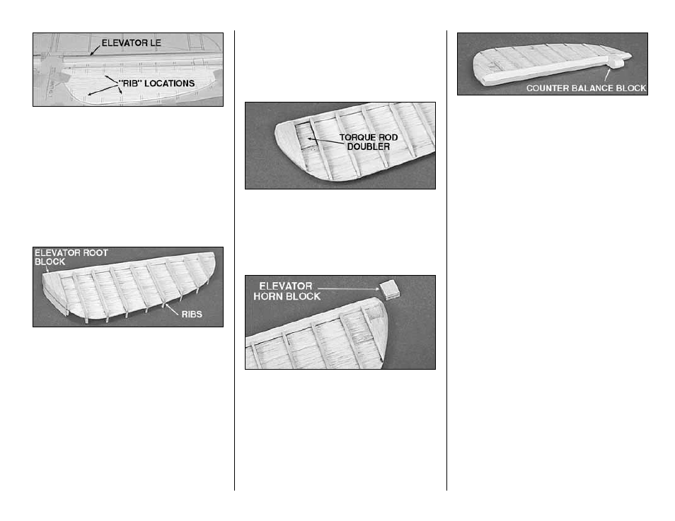
the die-cut 1/4” balsa Elevator LE (E). Draw two
parallel lines 1/16” away from center line on the aft
side.
❑ ❑
3. Hold the Elevator Base centered
between the lines on the Elevator LE. Use CA to
glue the Elevator Base to the LE.
❑ ❑
4. Cut “ribs” from the 3/32” x 3/8” x 36”
balsa sticks and glue them onto both sides of the
elevator base at the locations you previously
marked.
❑ ❑
5. Glue a 3/8” thick shaped balsa
Elevator Root block to each side of the Elevator
Base.
❑ ❑
6. Refer to the photos on this page and the
cross-sections on the plans to obtain the shape of
the elevators. Use a razor plane and sanding
block to “rough in” the shape of the elevators. Trial
fit the elevators to the stab for final shaping.
❑ ❑
7. Glue a die-cut 1/8” balsa elevator
Torque Rod Doubler to both sides of the Elevator
Base as shown on the plans.
❑ ❑
8. Cut a pocket in the bottom of the right
elevator to match the 1/4” x 1/2” x 5/8” Elevator
Horn Block. Check the plans for the proper
location.
❑ ❑
9. Glue, using 6-minute epoxy, the birch
plywood Elevator Horn Block in the pocket on the
bottom side of the right elevator. Shape the
Elevator Horn Block edge to match the elevator.
❑ ❑
10. Place the elevator over the plans and
mark position of the 5/8” x 5/8” x 11/16” balsa
Counter Balance Block on the elevator LE. Glue
the Counter Balance Block in place. Shape the
front of the block to a full radius. Allow
approximately 1/16” clearance on both sides of the
counter balance block in the stab opening.
❑ ❑
11. Shape the Elevator LE to a “V”
shape to allow elevator travel. See the cross-
section on the plans for the correct shape.
❑ ❑
12. Tape the elevators to the stabilizer.
Hold the bent 1/8” Elevator Joiner Wire up to the
elevator and mark the location of the holes (see
the plans for the joiner location).
❑ ❑
13. Remove the elevators from the
stabilizer. Drill 1/8” holes in the elevators for the
Joiner wire. Make slots inboard of the holes to
allow the wire to be inset into the elevators.
❑ ❑
14. Test fit the joiner wire into the
elevators. Check to see if the elevators align with
each other properly. Make adjustments if required.
BUILD THE RUDDER
❑
1. Glue the two die-cut 3/16” balsa Rudder
LE’s together with CA+. Even up the edges with a
sanding block, but save any tapering for later.
- 13 -