Top Flite TOPA0120 User Manual
Page 31
Fuselage Bolt Blocks into the notches in the
fuselage side doublers at Former F-4. Use epoxy
to make a small fillet around the sides of the bolt
blocks. Also make an epoxy fillet between the bolt
block and Former F-4.
❑
16. Use CA+ to finish gluing the fuselage sides
to Formers F-1B, F-2, F-3 and F-4.
❑
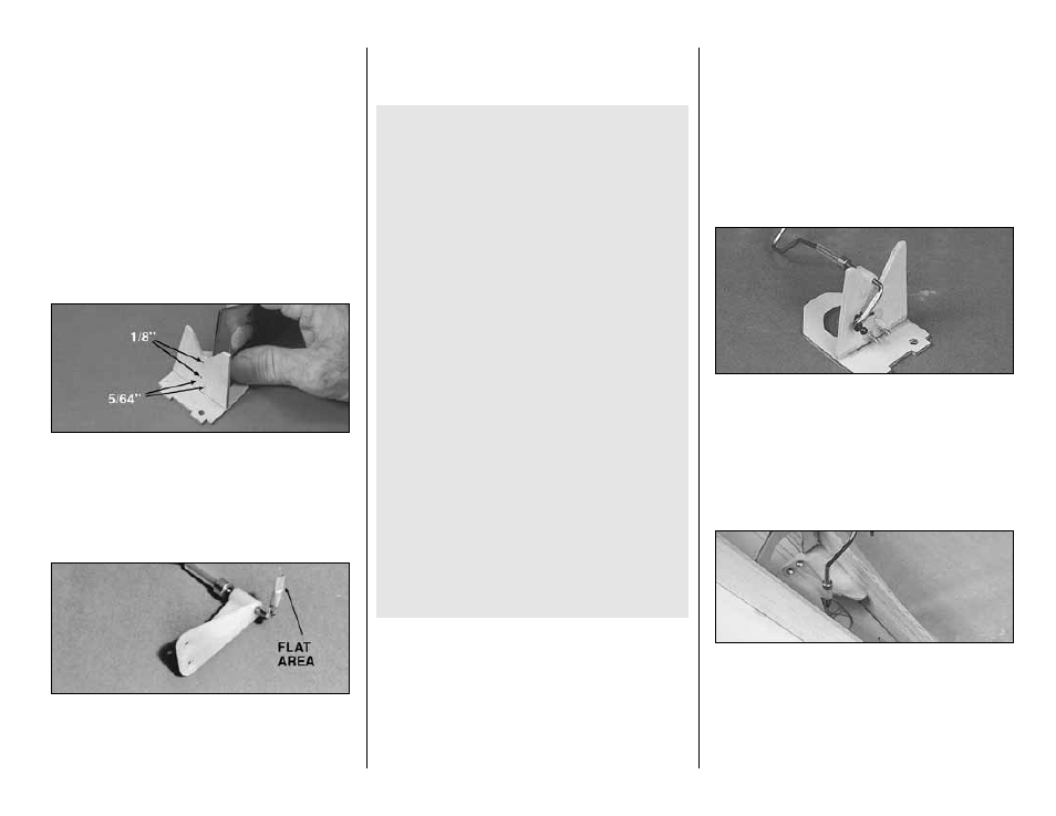
17. Drill 5/64” holes through the forward two
punch marks in the die-cut 1/8” plywood Tail
Wheel Plate (TW). Drill 1/8” holes through the two
AFT punch marks for nylon tail wheel support pegs
(see below).
❑
18. Glue the die-cut 1/8” plywood Tail Wheel
Plate (TW) to former F-8, making sure they are
perpendicular. Make sure the number on F-8
faces down.
❑
19. Place the 5/8” long piece of 1/8” O.D.
brass tubing over the top end of the wire. Squeeze
the exposed end of the tube firmly with pliers to
flatten it. Check the parts over the fuselage top
view to make sure they match up well. Silver
solder the brass tube to the wire (see below).
TIPS FOR SILVER SOLDERING
Use this process when soldering metal to metal
such as brass tube to wire, or pushrod ends to
wire.
A. Thoroughly clean the items to be soldered with
alcohol or degreasing solvent.
B. Roughen the area to be soldered with fine
sandpaper, then clean again.
C. Assemble the items to be soldered.
D. Apply a small amount of soldering flux. Acid
based flux works best when one or more of the
items is steel.
E. Heat the metal with a soldering gun or iron, and
apply solder to the metal. The metal must get
hot enough to melt the solder and the solder
must flow freely into the joint.
F. Do not move the parts until the solder has
cooled.
G. Clean off the excess flux with alcohol or
solvent. Coat the parts with a very fine film of
oil.
H. Test the joint by pulling hard.
❑
20. Mark the location for mounting the Metal
Ball on the flat of the Brass Tube. Drill a 1/16"
hole at the mark.
❑
21. Attach the ball permanently on the tail gear
with the Small Nut provided. Put a drop of
6-minute epoxy on the threads to prevent it from
vibrating loose.
❑
22. Use the 4-40 Set Screw to set the collar at
the height shown on the fuselage side view, but
orient the set screw so small adjustments can be
made later if required.
❑
23. Roughen the tubular Nylon Bearing on
the tail wheel wire with sandpaper so glue will stick
to it.
❑
24. Put a small drop of 6-minute epoxy on the
Nylon Bracket where the bolt holes are. Screw the
Nylon Bracket to TW with two #4 x 3/8” Sheet
Metal Screws. Then put a drop of epoxy on the
threads of the Sheet Metal Screws to prevent them
from vibrating loose.
❑
25. Pin the die-cut 1/8” plywood Stab Support
Crutch to the plans at its location. The fuselage
sides will protrude aft of the Stab Support Crutch
by approximately 3/8”. Glue F-8 to the front edge
of the Stab Support Crutch; it should be
perpendicular to the building board.
- 31 -