Toa M-864D User Manual
Page 9
9
17
18
19
20
21
22
15
16
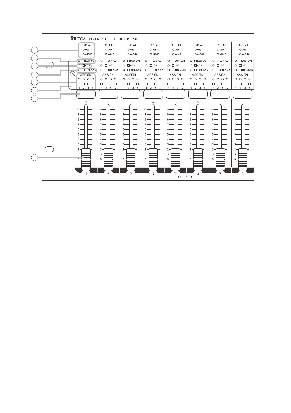
15. Input level indicators [–40 dB, 0 dB, PEAK]
(Green, red)
Light green depending on the input signal level.
(Peak indicator lights red.)
Input level indicates the pre-fader level value.
Adjust the input gain when the PEAK indicator
remains lit. (See p. 16, "PHANTOM POWER,
16. Low cut switch and Low cut indicator
[LOW CUT] (Green)
The indicator lights when the switch is pressed
and the internal low cut filter is enabled.
Cutoff frequency: 100 Hz*
* It can be adjusted in the range of 20 Hz to 20
kHz using the supplied M-864D PC Software.
(See the M-864D Software instructions.)
17. Feedback Suppressor switch and Feedback
suppressor indicator [FBS] (Green)
The Feedback Suppression function is enabled
when this switch is pressed, and the indicator
lights. (See p. 27.)
18. Tone/Gain selection switch and Tone/Gain
control mode indicator [TONE/GAIN] (Green,
orange)
Each time the switch is pressed, the mode
switches among Standby mode, Tone control
mode, and Gain control mode.
The indicator goes off in Standby mode, lights
green in Tone control mode, and lights orange in
Gain control mode.
19. Assignment switches and Assignment
indicators [ASSIGN 1 – 4] (Green)
Used to select the output destination of the post-
fader signals adjusted by the monaural input
volume fader (22) of each channel.
The corresponding indicator lights when the
switch is pressed, and the monaural input (1
through 8) signal is output to the corresponding
bus (1 through 4).
20. Protective cover (accessory)
Used to protect settings such as Low cut switch
(16) and Assignment switch (19) settings.
21. Input name label attaching space
Affix the label with the printed input name.
22. Monaural input volume fader [INPUT 1 – 8]
Adjusts the monaural input volume level.
The volume level increases by moving up the
fader, and decreases by moving it down.
• Section B