Toa M-864D User Manual
Page 10
10
• Section C
25
26
27
28
29
23
24
22
30
31
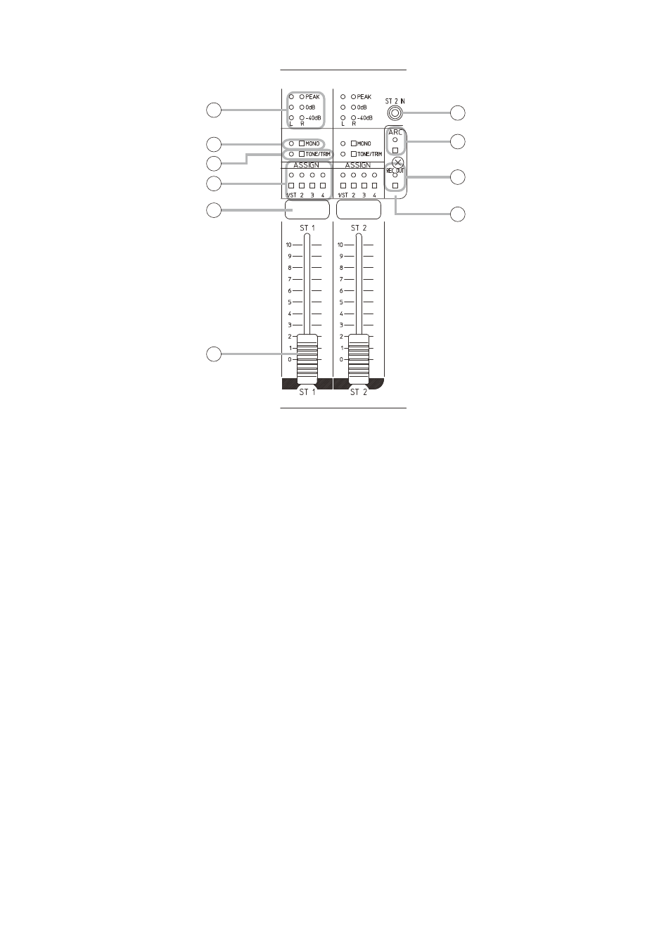
23. Input level indicators [–40 dB, 0 dB, PEAK]
(Green, red)
Light green depending on the input signal level.
(The peak indicator lights red.) Input level indicates
the pre-fader level value.
Adjust the trim control when the PEAK indicator
remains lit. (See p. 19, "TRIM CONTROL.")
The ST1 L channel’s input level indicator shows
the total level of 3 inputs (A, B, and C) provided at
the STEREO INPUT 1 L channel.
Likewise, the ST1 R channel’s input level indicator
shows the total level of 3 inputs (A, B, and C)
provided at the R channel.
The ST2 L channel and the ST2 R channel indicate
the levels in the same way.
24. Monaural summing switch and Monaural
summing indicator [MONO] (Green)
The indicator lights when the switch is pressed,
and stereo input signals applied to L and R
channels can be mixed and output (monaural).
(See p. 23.)
25. Tone/Trim selection switch and Tone/Trim
control mode indicator [TONE/TRIM]
(Green, orange)
Each time the switch is pressed, the mode
switches among Standby mode, Tone control
mode, and Gain control mode.
The indicator goes off in Standby mode, lights
green in Tone control mode, and lights orange in
Trim control mode.
26. Assignment switches (Stereo) and Assignment
indicators [1 – 4] (Green)
Used to select the output destination of the post-
fader signals adjusted using the stereo input
volume fader (28) of each channel.
The corresponding indicator lights when the switch
is pressed, and the signals applied to the Stereo
input 1 and 2 are output to the corresponding bus
(1 through 4).
1/ST: Outputs L channel signals from the Output 1.
2: Outputs R channel signals from the Output 2.
3: Outputs L + R channels signals from the
Output 3.
4: Outputs L + R channels signals from the
Output 4.
Note
With the switch “1/ST” or “2” pressed, pressing
the Monaural summing switch (24) causes the
input signals to be mixed and sent as summing
output, outputting the L + R channels signals to
the Output 1 and 2 individually.
27. Input name label attaching space
Affix the label with the printed input name.
28. Stereo input volume fader [ST 1 – 2]
Adjusts the stereo input volume level.
The volume level increases by moving up the
fader and decreases by moving it down.