Rear terminal section – Toa M-864D User Manual
Page 11
11
29. Front-mounted Stereo input 2 jack [ST 2 IN]
–10 dB*, 10 kΩ, unbalanced type, stereo mini jack.
It is internally connected in parallel to the Stereo
input 2. Adjust the input level with the Stereo 2
Input volume fader (28).
30. ARC switch and ARC operation indicator
[ARC] (Green)
Press this switch to enable the Automatic
Resonance Control function (ARC).
Hold down this switch for 3 seconds to start
the ARC measurement, and the ARC operation
indicator flashes.
Upon measurement completion, the ARC filter is
set, and the ARC indicator lights. (See p. 28.)
31. Recording output switch and Recording
output indicator [REC OUT] (Green)
The indicator lights when the switch is pressed,
and the Control knob (6) is allowed to adjust the
recording output volume. (See p. 25.)
* 0 dB = 0.775 V
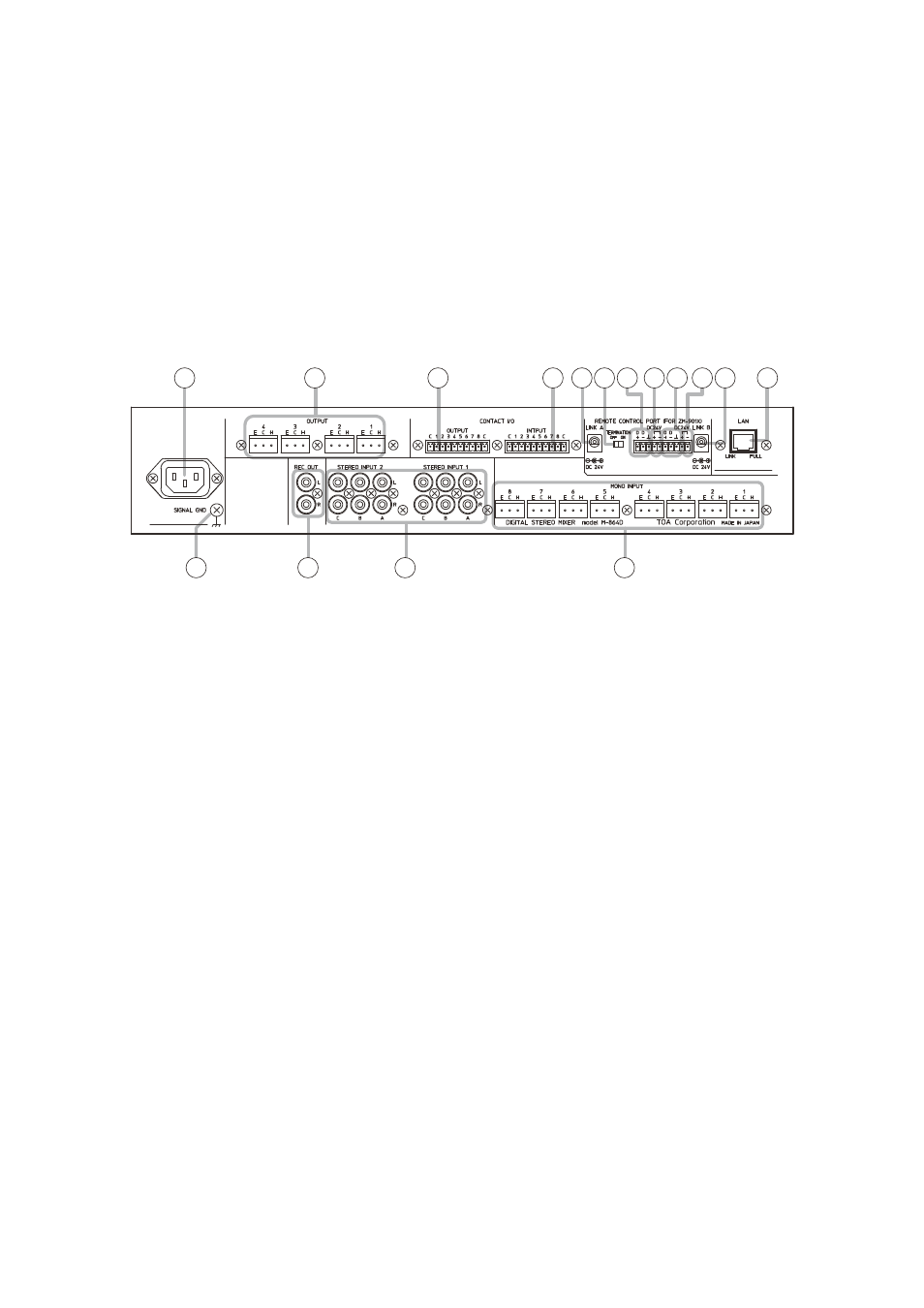
[Rear terminal section]
32
33
34
35 36
36
37 38
38
39
39
40
41
42
43
44
32. AC inlet
Connect this inlet to the AC wall outlet using the
supplied dedicated power cord.
33. Output terminals [OUTPUT 1 – 4]
+ 4 dB*, 600 Ω, balanced type, removable terminal
block.
The input channel signals assigned to Buses
1 through 4 using the Assignment switches (19
and 26) are output from each individual output
terminal.
Buses 1 through 4 correspond to the output
terminals 1 through 4, respectively.
34. Contact output terminals [OUTPUT C, 1, 2, 3,
4, 5, 6, 7, 8, C]
Removable terminal block, 8-channel contact
output terminal.
Perform function assignment to each contact by a
PC using the supplied M-864D PC Software.
35. Contact input terminals [INPUT C, 1, 2, 3, 4, 5,
6, 7, 8, C]
Removable terminal block, 8-channel contact
input terminals.
Perform function assignment to each contact by a
PC using the supplied M-864D PC Software.
36. AC adapter input [LINK A and LINK B]
Connect the dedicated AC adapter or its
equivalent* that supplies 24 V DC power to the
ZM Remote controller.
* Use the AD-246 AC adapter (optional) or its
equivalent. As for the usable adapter, consult
your TOA dealer.
37. Termination switch [TERMINATION ON, OFF]
Used to turn ON or OFF the termination of 120 Ω
for parallel connection.
38. Data line connection terminals [D+, D–]
Connect the data line from the ZM Remote
controller to these terminals.
Match the polarity.
39. 24 V DC output terminals [DC 24 V, + and –]
Supply 24 V DC to the ZM Remote controller.
40. LAN port
Connect this port to the LAN-connected switching
hub using a LAN cable.
The MX-864D’s default IP address is “192.168.14.1.”
Perform settings by a PC using the supplied
M-864D PC Software.
• Link indicator
Lights when the link is established and during
data transmission or reception.
• Full indicator
Lights during Full duplex operation.
41. Functional ground terminal
Connect this terminal to the functional ground of
external equipment if much noise is encountered
when the digital audio processor is connected
to the external equipment. The noise may be
reduced
Note: This ground is not for protective ground.