Carrier 48TCA04---A12 User Manual
Page 62
62
graph with the left side of the chart to determine that the
range configuration for the CO
2
sensor should be 1800
ppm. The EconoMi$er IV controller will output the 6.7
volts from the CO
2
sensor to the actuator when the CO
2
concentration in the space is at 1100 ppm. The DCV
setpoint may be left at 2 volts since the CO
2
sensor
voltage will be ignored by the EconoMi$er IV controller
until it rises above the 3.6 volt setting of the minimum
position potentiometer.
Once the fully occupied damper position has been
determined, set the maximum damper demand control
ventilation potentiometer to this position. Do not set to the
maximum position as this can result in over-ventilation to
the space and potential high humidity levels.
CO
2
Sensor Configuration
The CO
2
sensor has preset standard voltage settings that
can be selected anytime after the sensor is powered up.
(See Table 28.)
Use setting 1 or 2 for Carrier equipment. (See Table 28.)
1. Press Clear and Mode buttons. Hold at least 5
seconds until the sensor enters the Edit mode.
2. Press Mode twice. The STDSET Menu will appear.
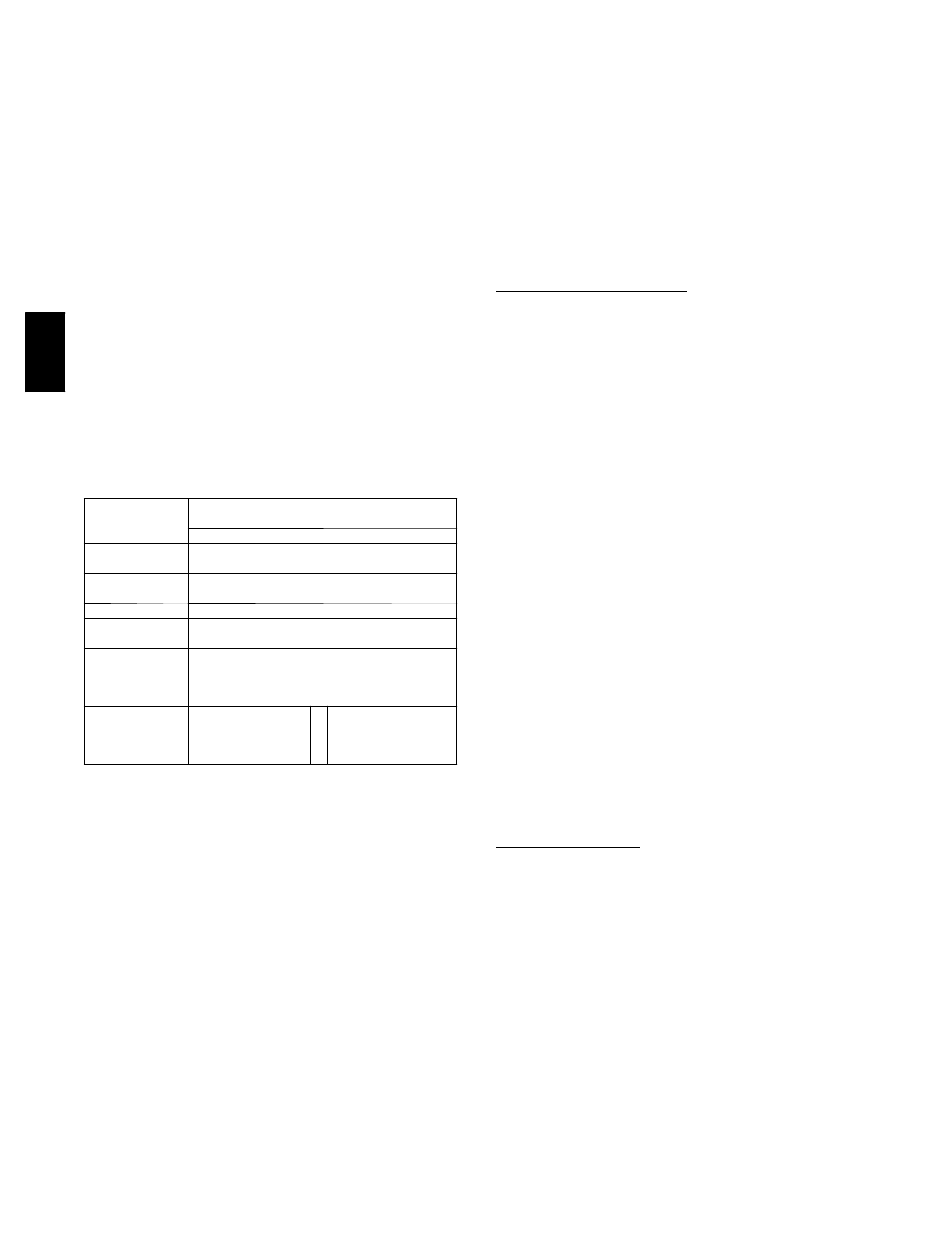
Table 28 – EconoMi$er IV Sensor Usage
APPLICATION
ECONOMI$ER IV WITH OUTDOOR AIR DRY
BULB SENSOR
Accessories Required
Outdoor Air
Dry Bulb
None. The outdoor air dry bulb sensor is
factory installed.
Differential
Dry Bulb
CRTEMPSN002A00*
Single Enthalpy
HH57AC078
Differential
Enthalpy
HH57AC078 and CRENTDIF004A00*
CO
2
for DCV
Control using a
Wall-Mounted
CO
2
Sensor
33ZCSENCO2
CO
2
for DCV
Control using a
Duct-Mounted
CO
2
Sensor
33ZCSENCO2† and
33ZCASPCO2**
O
R CRCBDIOX005A00††
* CRENTDIF004A00 and CRTEMPSN002A00 accessories are
used on many different base units. As such, these kits may
contain parts that will not be needed for installation.
† 33ZCSENCO2 is an accessory CO
2
sensor.
** 33ZCASPCO2 is an accessory aspirator box required for duct-
mounted applications.
†† CRCBDIOX005A00 is an accessory that contains both
33ZCSENCO2 and 33ZCASPCO2 accessories.
3. Use the Up/Down button to select the preset
number. (See Table 28.)
4. Press Enter to lock in the selection.
5. Press Mode to exit and resume normal operation.
The custom settings of the CO
2
sensor can be changed
anytime after the sensor is energized. Follow the steps
below to change the non-standard settings:
1. Press Clear and Mode buttons. Hold at least 5
seconds until the sensor enters the Edit mode.
2. Press Mode twice. The STDSET Menu will appear.
3. Use the Up/Down button to toggle to the NONSTD
menu and press Enter.
4. Use the Up/Down button to toggle through each of
the nine variables, starting with Altitude, until the
desired setting is reached.
5. Press Mode to move through the variables.
6. Press Enter to lock in the selection, then press Mode
to continue to the next variable.
Dehumidification of Fresh Air with DCV (Demand
Controlled Ventilation) Control
If normal rooftop heating and cooling operation is not
adequate for the outdoor humidity level, an energy
recovery unit and/or a dehumidification option should be
considered.
EconoMi$er IV Preparation
This procedure is used to prepare the EconoMi$er IV for
troubleshooting. No troubleshooting or testing is done by
performing the following procedure.
NOTE:
This procedure requires a 9--v battery, 1.2
kilo--ohm resistor, and a 5.6 kilo--ohm resistor which are
not supplied with the EconoMi$er IV.
IMPORTANT: Be sure to record the positions of all
potentiometers before starting troubleshooting.
1. Disconnect power at TR and TR1. All LEDs should
be off. Exhaust fan contacts should be open.
2. Disconnect device at P and P1.
3. Jumper P to P1.
4. Disconnect wires at T and T1. Place 5.6 kilo--ohm
resistor across T and T1.
5. Jumper TR to 1.
6. Jumper TR to N.
7. If connected, remove sensor from terminals SO and +.
Connect 1.2 kilo--ohm 4074EJM checkout resistor
across terminals SO and +.
8. Put 620--ohm resistor across terminals SR and +.
9. Set minimum position, DCV setpoint, and exhaust po-
tentiometers fully CCW (counterclockwise).
10. Set DCV maximum position potentiometer fully CW
(clockwise).
11. Set enthalpy potentiometer to D.
12. Apply power (24 vac) to terminals TR and TR1.
Differential Enthalpy
To check differential enthalpy:
1. Make sure EconoMi$er IV preparation procedure has
been performed.
2. Place 620--ohm resistor across SO and +.
3. Place 1.2 kilo--ohm resistor across SR and +. The
Free Cool LED should be lit.
4. Remove 620--ohm resistor across SO and +. The Free
Cool LED should turn off.
5. Return EconoMi$er IV settings and wiring to normal
after completing troubleshooting.
48TC