Carrier 48TCA04---A12 User Manual
Page 36
36
Table 15 – Thermistor Resistance vs Temperature
Values for Space Temperature Sensor, Supply Air
Temperature Sensor, and Outdoor Air Temperature
Sensor
TEMP
(C)
TEMP
(F)
RESISTANCE
(Ohms)
---40
---40
335,651
---35
---31
242,195
---30
---22
176,683
---25
---13
130,243
---20
---4
96,974
---15
5
72,895
---10
14
55,298
---5
23
42,315
0
32
32,651
5
41
25,395
10
50
19,903
15
59
15,714
20
68
12,494
25
77
10,000
30
86
8,056
35
95
6,530
40
104
5,325
45
113
4,367
50
122
3,601
55
131
2,985
60
140
2,487
65
149
2,082
70
158
1,752
NOTE: The sensor must be mounted in the discharge
airstream downstream of the cooling coil and any heating
devices. Be sure the probe tip does not come in contact
with any of the unit’s heater surfaces.
Outdoor Air Temperature (OAT) Sensor — The OAT is
factory--mounted in the EconoMi$er 2 (FIOP or
accessory). It is a nominal 10k ohm thermistor attached to
an
eyelet
mounting
ring.
See
Table
15
for
temperature--resistance characteristic.
EconoMi$er 2 — The PremierLink control is used with
EconoMi$er 2 (option or accessory) for outdoor air
management. The damper position is controlled directly
by the PremierLink control; EconoMi$er 2 has no internal
logic device.
Outdoor air management functions can be enhanced with
field--installation of these accessory control devices:
Enthalpy control (outdoor air or differential sensors)
Space CO
2
sensor
Outdoor air CO
2
sensor
Refer to Table 16 for accessory part numbers.
Field connections — Field connections for accessory
sensor and input devices are made at the 16--pole terminal
block (TB1) located on the control box bottom shelf in
front of the PremierLink control. Some input devices also
require a 24--vac signal source; connect at LCTB terminal
R at “THERMOSTAT” connection strip for this signal
source. See connections figures on following pages for
field connection locations (and for continued connections
at the PremierLink board inputs).
Table 17 provides a summary of field connections for
units equipped with Space Sensor. Table 18 provides a
summary of field connections for units equipped with
Space Thermostat.
Space Sensors -- The PremierLink controller is
factory--shipped configured for Space Sensor Mode. A
Carrier T--55 or T--56 space sensor must be used. T--55
space temperature sensor provides a signal of space
temperature to the PremierLink control T--56 provides
same space temperature signal plus it allows for
adjustment of space temperature setpoints from the face of
the sensor by the occupants. See Table 15 for temperature
versus resistance characteristic on the space sensors.
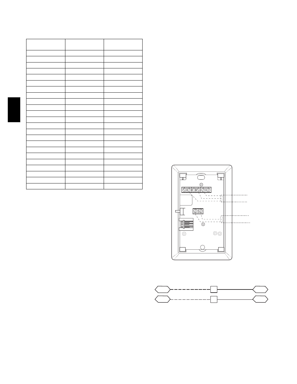
Connect T--55 -- See Fig. 43 for typical T--55 internal
connections. Connect the T--55 SEN terminals to TB1
terminals 1 and 3 (see Fig. 44).
2
3
4
5
6
1
SW1
SEN
BRN (GND)
BLU (SPT)
RED(+)
WHT(GND)
BLK(-)
CCN COM
SENSOR WIRING
C08201
Fig. 43 -- T--55 Space Temperature Sensor Wiring
SEN
J6-7
J6-6
1
3
TB1
PL
SEN
C08212
Fig. 44 -- PremierLink T--55 Sensor
48TC