Protective devices, Gas heating system, Compressor protection – Carrier 48TCA04---A12 User Manual
Page 22: Relief device, Control circuit, 24--v, General
22
Controller’s Power LED is Off
1. Make sure the circuit supplying power to the control-
ler is operational. If not, make sure JP2 and JP3 are
set correctly on the controller before applying power.
2. Verify that power is applied to the controller’s supply
input terminals. If power is not present, replace or re-
pair wiring as required.
Remote Test/Reset Station’s Trouble LED Does Not
flash When Performing a Dirty Test, But the Control-
ler’s Trouble LED Does
1. Verify that the remote test/station is wired as shown
in Fig. 24. Repair or replace loose or missing wiring.
2. Configure the sensor dirty test to activate the control-
ler’s supervision relay. See “Changing sensor dirty
test operation.”
Sensor’s Trouble LED is On, But the Controller’s
Trouble LED is OFF
Remove JP1 on the controller.
PROTECTIVE DEVICES
Compressor Protection
Overcurrent
The compressor has internal linebreak motor protection.
Overtemperature
The compressor has an internal protector to protect it
against excessively high discharge gas temperatures.
High Pressure Switch
The system is provided with a high pressure switch
mounted on the discharge line. The switch is
stem--mounted and brazed into the discharge tube. Trip
setting is 630 psig +/-- 10 psig (4344 +/-- 69 kPa) when
hot. Reset is automatic at 505 psig (3482 kPa).
Low Pressure Switch
The system is protected against a loss of charge and low
evaporator coil loading condition by a low pressure switch
located on the suction line near the compressor. The
switch is stem--mounted. Trip setting is 54 psig +/-- 5 psig
(372 +/-- 34 kPa). Reset is automatic at 117 +/-- 5 psig
(807 +/-- 34 kPa).
Evaporator Freeze Protection
The system is protected against evaporator coil frosting
and low temperature conditions by a temperature switch
mounted on the evaporator coil hairpin. Trip setting is
30_F +/-- 5_F (--1_C +/-- 3_C). Reset is automatic at 45_F
(7_C).
Supply (Indoor) Fan Motor Protection
Disconnect and lockout power when servicing fan motor.
The standard supply fan motor is equipped with internal
overcurrent and overtemperature protection. Protection
devices reset automatically.
The High Static option supply fan motor is equipped with
a pilot--circuit Thermix combination overtemperature/
overcurrent protection device. This device resets
automatically. Do not bypass this switch to correct
trouble. Determine the cause and correct it.
Condenser Fan Motor Protection
The condenser fan motor is internally protected against
overtemperature.
Relief Device
A soft solder joint at the suction service access port
provides pressure relief under abnormal temperature and
pressure conditions (i.e., fire in building). Protect this
joint during brazing operations near this joint.
Control Circuit, 24--V
The control circuit is protected against overcurrent
conditions by a circuit breaker mounted on control
transformer TRAN. Reset is manual.
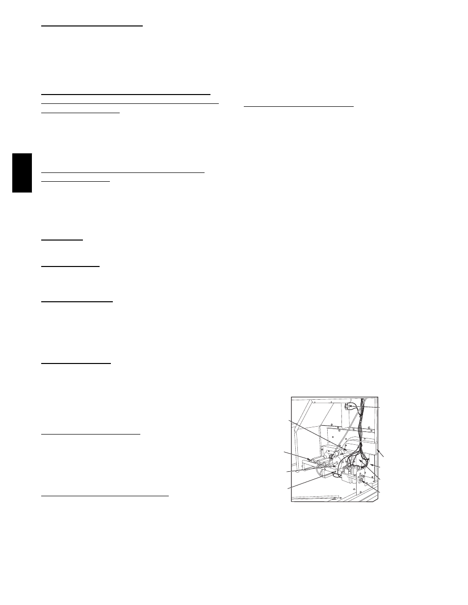
GAS HEATING SYSTEM
General
The heat exchanger system consists of a gas valve feeding
multiple inshot burners off a manifold. The burners fire
into matching primary tubes. The primary tubes discharge
into combustion plenum where gas flow converges into
secondary tubes. The secondary tubes exit into the
induced draft fan wheel inlet. The induced fan wheel
discharges into a flue passage and flue gases exit out a
flue hood on the side of the unit. The induced draft fan
motor includes a Hall Effect sensor circuit that confirms
adequate wheel speed via the Integrated Gas Control
(IGC) board. Safety switches include a Rollout Switch (at
the top of the burner compartment) and a limit switch
(mounted through the fan deck, over the tubes). (See Fig.
27 and Fig. 28.)
INDUCED-
DRAFT
MOTOR
MOUNTING
PLATE
INDUCED-
DRAFT
MOTOR
MANIFOLD
PRESSURE
TAP
VESTIBULE
PLATE
FLUE
EXHAUST
ROLLOUT
SWITCH
BLOWER
HOUSING
GAS
VALVE
BURNER
SECTION
C06152
Fig. 27 -- Burner Section Details
48TC