Carrier 48TCA04---A12 User Manual
Page 39
39
PremierLink Configuration screen for Operating Mode.
Default setting is Sensor Mode (value 1). Change the
value to 0 to reconfigure the controller for Thermostat
Mode.
When the PremierLink is configured for Thermostat
Mode, these functions are not available: Fire Shutdown
(FSD), Remote Occupied (RMTOCC), Compressor Safety
(CMPSAFE), Supply Fan Status (SFS), and Filter Pressure
Switch (FILTER).
Economizer controls —
Outdoor Air Enthalpy Control (PNO HH57AC077) --
The enthalpy control (HH57AC077) is available as a
field--installed accessory to be used with the EconoMi$er2
damper system. The outdoor air enthalpy sensor is part of
the enthalpy control. (The separate field--installed
accessory return air enthalpy sensor (HH57AC078) is
required for differential enthalpy control. See below.)
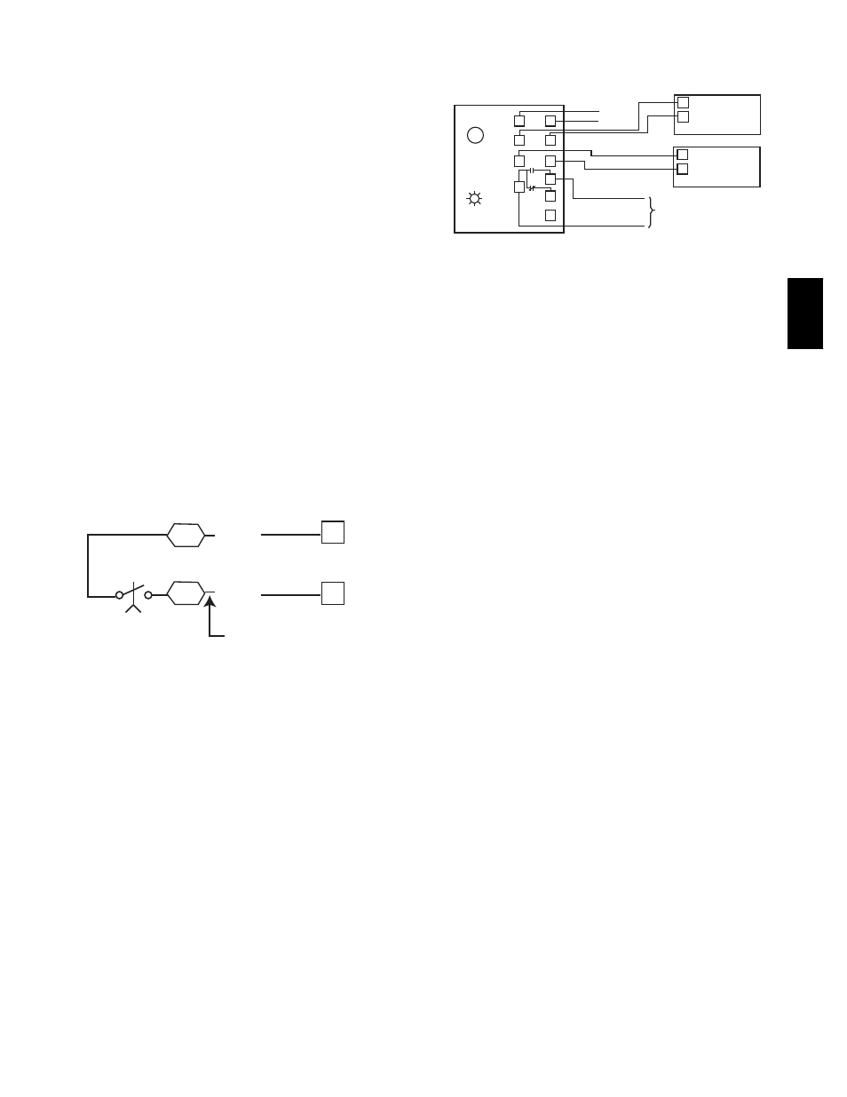
Locate the enthalpy control in the economizer hood.
Locate two GRA leads in the factory harness and connect
these leads to enthalpy control sensors 2 and 3. See Fig.
48. Connect the enthalpy control power input terminals to
economizer actuator power leads RED (connect to TR)
and BLK (connect to TR1).
6
7
LCTB
ECON
3
2
Enthalpy
Switch
GRA
GRA
Factory Wiring Harness
C08218
Fig. 48 -- Enthalpy Switch (HH57AC077) Connections
The outdoor enthalpy changeover setpoint is set at the
enthalpy controller.
The enthalpy control receives the outdoor air enthalpy
from the outdoor air enthalpy sensor and provides a dry
contact switch input to the PremierLink controller. A
closed contact indicates that outside air is preferred to the
return air. An open contact indicates that the economizer
should remain at minimum position.
Differential Enthalpy Control — Differential enthalpy
control is provided by sensing and comparing the outside
air and return air enthalpy conditions. Install the outdoor
air enthalpy control as described above. Add and install a
return air enthalpy sensor.
Return Air Enthalpy Sensor — Mount the return--air
enthalpy sensor (HH57AC078) in the return--air duct. The
return air sensor is wired to the enthalpy controller
(HH57AC077). See Fig. 49.
LED
A
B
C
D
TR
TR1
SO
SR
2
3
1
+
+
BRN
RED
GRAY/ORN
GRAY/RED
WIRE HARNESS
IN UNIT
BLK
RED
S
+
(RETURN AIR
ENTHALPY
SENSOR)
S
+
(OUTDOOR
AIR
ENTHALPY
SENSOR)
ENTHALPY CONTROLLER
NOTES:
1. Remove factory-installed jumper across SR and + before connecting
wires from return air sensor.
2. Switches shown in high outdoor air enthalpy state. Terminals 2 and 3
close on low outdoor air enthalpy relative to indoor air enthalpy.
3. Remove sensor mounted on back of control and locate in outside air-
stream.
C06019
Fig. 49 -- Outside and Return Air Enthalpy Sensor
Wiring
To wire the return air enthalpy sensor, perform the
following:
1. Use a 2--conductor, 18 or 20 AWG, twisted pair cable
to connect the return air enthalpy sensor to the enthal-
py controller.
2. At the enthalpy control remove the factory--installed
resistor from the (SR) and (+) terminals.
3. Connect the field--supplied RED wire to (+) spade
connector on the return air enthalpy sensor and the
(SR+) terminal on the enthalpy controller. Connect
the BLK wire to (S) spade connector on the return air
enthalpy sensor and the (SR) terminal on the enthalpy
controller.
NOTE: The enthalpy control must be set to the “D”
setting for differential enthalpy control to work properly.
The enthalpy control receives the indoor and return
enthalpy from the outdoor and return air enthalpy sensors
and provides a dry contact switch input to the
PremierLink controller. A closed contact indicates that
outside air is preferred to the return air. An open contact
indicates that the economizer should remain at minimum
position.
Indoor Air Quality (CO
2
sensor) — The indoor air quality
sensor accessory monitors space carbon dioxide (CO
2
)
levels. This information is used to monitor IAQ levels.
Several types of sensors are available, for wall mounting
in the space or in return duct, with and without LCD
display, and in combination with space temperature
sensors. Sensors use infrared technology to measure the
levels of CO
2
present in the space air.
The CO
2
sensors are all factory set for a range of 0 to
2000 ppm and a linear mA output of 4 to 20. Refer to the
instructions supplied with the CO
2
sensor for electrical
48TC