Caution – Reznor R6GN Option - Installation - High Static Blower Drive - Light Commercial User Manual
Page 7
7
Mounting Split Taper Bushings in Split Taper Bushed
Pulleys
Pre- Installation
• Make sure the shaft, bushing barrel & bore, split taper pulley
bore, keys and keyways are free of burrs, paint, etc.
• The bushing may fi rst be loosely installed into the split taper
bored pulley, and then the assembly slid onto the shaft.
For heavier pulley’s, it may be easier to either fi rst slide the
bushing onto the shaft and then slide the pulley onto the
bushing; however, if the bushing barrel has collapsed, it
must be wedged open. See Figure 4.
CAUTION:
Excessive wedging forces in bushing saw slot may
damage or break bushing.
• It may be necessary to slightly wedge open the saw slot
(Figure 5) on some bushings in order to start the bore and
position the bushing onto the shaft. A narrow edged regular
screw driver may be used.
Pulley Installation
1. Align the keyway in the bushing bore with the shaft keyway
and install the key. Make sure the key runs the entire length
of the bushing bore. See Figure 5.
2. Position the pulley so the keyway in the bore is aligned with
the external (barrel) key in the bushing. NOTE: Bushings do
not have an external key. The threaded holes in the pulley
must be aligned with the non-threaded holes in the bushing
fl ange. Insert the cap screws through the non-threaded
holes in the bushing fl ange and thread them by hand into
the pulley three or four turns.
3. Position the bushing & pulley assembly axially on the shaft
such that it is aligned with its running mate. NOTE: Check
for adequate clearance between the assembly and other
nearby components (if applicable). Various shaft sizes are
listed in Table 5.
4. Install cap screws and tighten by hand fi rst. NOTE: If cap
screws were provided with the pulley, use them instead of
the ones provided with the bushing. Since tightening the cap
screws may affect the axial position of the pulley, confi rm
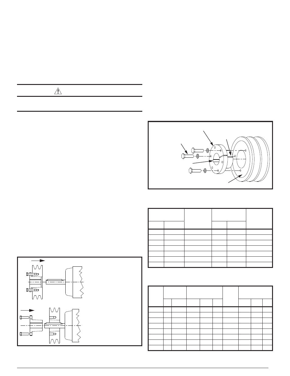
Split Taper Bushing
Split Taper Pulley
Cap Screws & Washers (3)
Keyway
Saw Slot
Figure 5. Split Taper Bushing & Pulley Assembly
Split Taper Pulley & Bushing
Components Assembled and
then Installed on Shaft
Split Taper Pulley & Bushing
Components Installed on
Shaft Individually
Figure 4. Split Taper Bushing & Pulley Assembly
Options
that the pulley is properly aligned with its running mate. If
not, determine how much the assembly must be moved into
proper alignment. Split taper tightening torques are listed
in Table 6.
5. If axial adjustment is required, fi rst attempt to move the
motor sheave to properly align the drive belt.
6. Check installation gap. NOTE: There must be a gap between
the bushing fl ange and the pulley face. If there is no gap
between them, disassemble the parts and determine the
reason(s) for the faulty assembly.
Pulley Removal
1. Remove all cap screws in sequence. If the bushing has a
keyway set screw, loosen it.
2. Insert cap screws in all threaded bushing fl ange holes.
Tighten the cap screws against the (hub) face of the pulley
until the screw force releases the pulley from the bushing.
3. Remove the bushing and pulley from the shaft.
SHAFT SIZE
RANGE (IN)
LOWER
SHAFT
SIZE LIMIT
(IN)
SHAFT SIZE
RANGE (IN)
LOWER
SHAFT
SIZE LIMIT
(MM)
Above
Through
Above
Through
–
1 1/2
-0.003
—
38.1
-0.076
1 1/2
2 1/2
-0.004
38.1
63.5
-0.102
2 1/2
4
-0.005
63.5
101.6
-0.127
4
6
-0.006
101.6
152.4
-0.152
6
8
-0.007
152.4
203.2
-0.178
8
9
-0.008
203.2
228.6
-0.203
9
—
-0.009
228.6
—
-0.229
Table 5. Shaft Size Limits for Split Taper Bushings
Bushing
SAE Grade 5
Cap Screw
Cap Screw Torque
Set
Screw
Size
Set Screw Torque
No.
Size
(in-Lbs) (Ft-Lbs) (N-M)
(in-Lbs) (Ft-Lbs) (N-M)
G;H
2
1/4-20NC
95
8
10.7
-
-
-
-
P;B
3
5/16-18NC
192
16
21.7
-
-
-
-
Q
3
3/8-16NC
348
29
39.3
5/16-18NC
165*
13.8* 18.6*
R
3
3/8-16NC
348
29
39.3
5/16-18NC
165
13.8
18.6
S
3
3/8-16NC
840
140
189.8
3/8-16NC
290
24.2
32.8
U
3
5/8-11NC
1680
140
189.8
3/8-16NC
290
24.2
32.8
W
4
3/4-10NC
3000
250
339.0
1/2-13NC*
620*
51.7* 70.1*
YO
4
1-8NC
7200
600
813.5
1/2-13NC*
620*
51.7* 70.1*
Table 6. Split Taper Tightening Torques