Jaypro Sports MHWM-D-A User Manual
Page 27
© 2005 Jaypro Sports Equipment JSL-Inst001 Rev G 10-24-2006
27 of 40
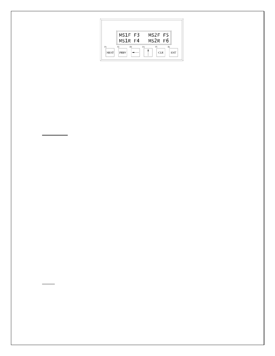
Figure 31: Manual Motor Starter Operating Mode
d. To operate motors manually, press and hold the buttons for the corresponding winch and
direction of travel:
MS1F = Motor Starter for Winch #1, Forward direction – F3 (o) button
MS1R = Motor Starter for Winch #1, Reverse direction – F4 (q) button
MS2F = Motor Starter for Winch #2, Forward direction – F5 (
CLR
) button
MS2R = Motor Starter for Winch #2, Reverse direction – F6 (
ENT
) button
Important: If at this point you notice that the winches operate in the opposite direction from
indicated, the phasing of your wiring may be reversed. Swapping two of the incoming leads can
change phasing of the hoist motors. Verify proper winch direction by watching the limit
switch rod. The down limit switch is located on the end of the winch closest to the motor –
the limit switch rod should travel away from the up limit (towards the lower limit) when
the hoist is paying out cable. Check this direction of operation immediately after
powering up the winch to avoid damage to limit switches or the hoist!
e. Run individual winches manually until load bar is level and approximately 3’ (36”) from floor
(may vary according to user preference or field conditions). Place a level on the load bar or
measure up from the floor at each cable attachment point to make sure load bar is exactly level.
f. Alternatively, load bar may be operated using the key switch. This will activate both winches
simultaneously, however, and is only recommended once unit has been leveled.
g. Using either a rolled mat or some other suitable temporary weights, load the bar and raise it just
enough to pick the weight up off the floor. This will ‘seat’ the cable into the grooves on the
hoist drum and avert accidental misalignment later during normal operation.
h. If while operating the key switch you notice the key must be in the ‘down’ position for the unit
to travel up, this means the wiring to the switch has been reversed. Correct the wiring before
proceeding.
Note: See troubleshooting guide at the end of this manual if for some reason the system is not
functioning as expected.