Load bar assembly – Jaypro Sports MHWM-D-A User Manual
Page 23
© 2005 Jaypro Sports Equipment JSL-Inst001 Rev G 10-24-2006
23 of 40
8. Load Bar Assembly
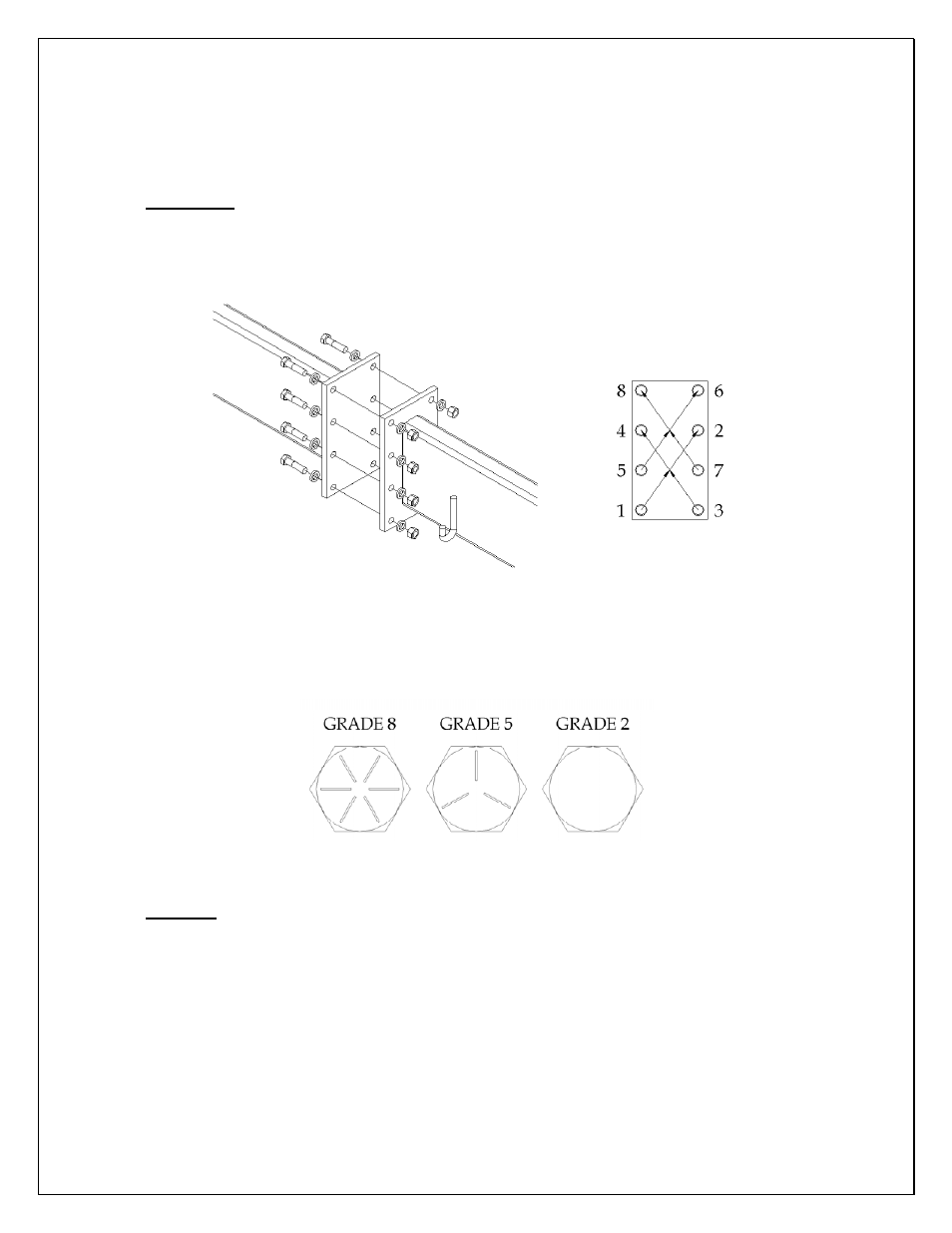
a. Lay out three pieces of the load bar on the floor under where the winches are installed. For both
splices, use eight (8) each hex head bolts, nuts, and lock washers as shown in drawing below,
and assemble the sections of the load bar together. Use a torque-tightening pattern as shown to
insure proper compression of lock washers. Repeat pattern as necessary until all bolts are tight.
Important: Bolt tightening and torquing sequence directly affects the stress on the splice plates
and alignment of the load bar sections. Be sure to follow the tightening pattern as shown to
minimize the amount of bow present in the assembled load bar. Torque for each bolt/nut should
be set to 110 ft-lbs.
Figure 23: Load Bar Splice Hardware Assembly & Bolt Tightening Sequence
b. No substitutions of factory provided hardware is allowed. Use only grade 8 nuts and bolts or
better. Diagram here shows head marking pattern for common hex head bolts. The higher the
grade number, the better the quality / higher strength of the steel.
Figure 24: Hex Bolt Grade Markings
Caution: Load bar weighs approximately 600 lbs by itself. Take great care in protecting
finished flooring during the assembly and hoisting operation. All personnel should wear
applicable safety equipment to prevent injury.
c. After loading the hoist bar for the first time with weights or rolled wrestling mats double check
all bolted connections and retighten as necessary.