Great Planes Piper J-3 Cub 20 Kit - GPMA0158 User Manual
Page 9
D 3. Refer to the plan, then cut six ribs from the
3/16" x 3/16" x 24" balsa stick. Position the ribs in the
stabilizer frame and glue in place with thin CA.
D 1. Carefully sand all the tail surfaces flat with 150-grit
sandpaper and a large sanding block or T-bar. Remove as
little material as possible and don't get carried
away - inspect your work as you proceed. It's easy to
sand a low spot into the ribs or trailing edge, so be
careful to avoid doing this.
D 2. Draw centerlines around the outside edges of the fin,
rudder, stabilizer and elevator to assist in sanding and
hinge installation.
D 4. Remove the stabilizer from the building board and
inspect all of the glue joints. Apply thick CA to any
open joints.
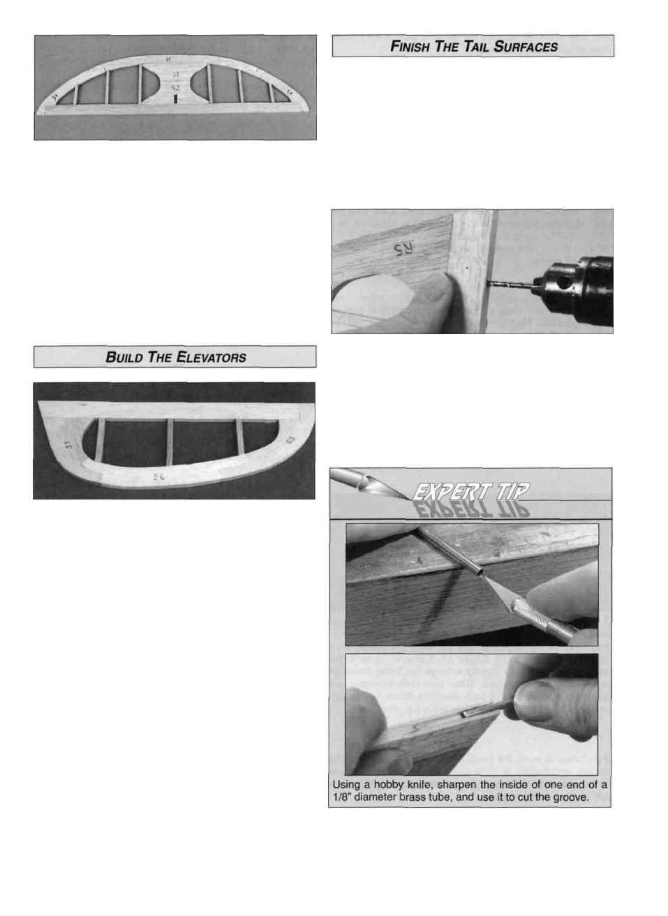
D D 1. Position the S5, S6 and S7 from the die-cut 3/16"
balsa parts over the plan and check the fit of the mating
edges and sand them as needed. Cut the elevator LE from
a 3/16" x 5/8" x 24" balsa stick. Pin the parts in place over
the plans and glue them together with thin CA.
D D 2. Refer to the plan, then cut three elevator ribs from
the 3/16" x 3/16" x 24" balsa stick. Position and glue the
ribs in the elevator frame with thin CA.
D D 3. Remove the elevator from the building board and
inspect all the glue joints. Apply thick CA to any open joints.
D 4. Repeat this process to build the other elevator.
D 3. Position the rudder over the plan and align the bent
wire tail gear over the bottom end of the rudder as shown.
Mark the tail gear "arm" location on the centerline of the
rudder LE. Drill a 7/64" hole, 3/4" deep at this spot (the hole
is drilled slightly oversize to create a hard epoxy "sleeve"
around the wire). Cut a groove from the tail gear hole to
the bottom of the rudder that will allow the nylon tail gear
bearing to fit flush with the LE of the rudder. Do not glue
the tail gear in at this time.
9