Great Planes Piper J-3 Cub 20 Kit - GPMA0158 User Manual
Page 30
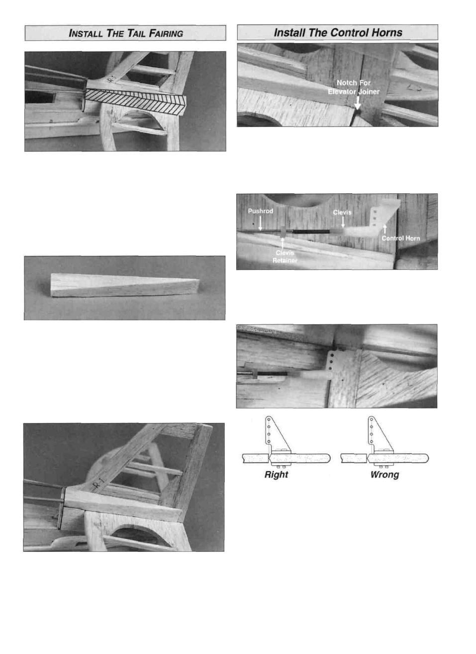
D 1. Trial fit the 5/8" x 3/4" x 5-1/4" balsa tail fairing
blocks on each side of the fin, on top of the stabilizer Sand
the front of the blocks to butt against turtle deck former
TF4 Mark a line on the top of both blocks from the outside
edge of TF4 to where the block meets the trailing edge of
the fin.
D 1 Temporarily attach the elevator and rudder to the
stabilizer and fin If you are using the CA hinges provided in
the kit and have not cut slots for them, attach the elevator
and rudder with masking tape Cut a notch in the leading
edge of the rudder to accommodate the joiner wire in
the elevator
D 2 Slide a silicone clevis retainer on the elevator and
rudder control rods Screw a nylon clevis 14 turns onto the
end of the rudder and elevator pushrods Install a nylon
control horn on each of the clevises.
D 2 Remove the tail fairing blocks and cut them to a
wedge shape with a razor saw.
D 3. Trace the outline made by former TF4 and the
stringers on the front face of each block Remove the
blocks and carve them to conform to the correct shape
D 4 Glue the tail fairing blocks in position and fill any gaps
with HobbyLite filler, then sand to shape to match former
TF4 and the 1/8" dowels.
D 3 Hold the control horn in position on the elevator (see
the sketch above for correct alignment) The pushrod
should not be bent and should slide smoothly in the outer
pushrod tube Mark the location for the horn screws on the
elevator Drill two 3/32" horn screw holes through the
elevator Use a T-pin to prick a few holes in the area under
the control horn and apply a drop or two of thin CA to the
pin holes to strengthen the balsa wood After the CA has
cured, install the control horn with the two #2-56 machine
screws and the backing plate Repeat this process for
the rudder.
30