Great Planes Piper J-3 Cub 20 Kit - GPMA0158 User Manual
Page 7
Inches x 25.4 = mm (conversion factor)
1 /64" = .4mm 3/4" = 19.0mm
1/32" = .8mm 1" = 25.4mm
1/16"= 1.6mm 2" = 50.8mm
3/32" = 2.4mm 3" = 76.2mm
1/8" = 3.2mm 6" = 152.4mm
5/32" = 4.0mm 12" = 304.8mm
3/16" = 4.8mm 18" = 457.2mm
1/4"= 6.4mm 21"= 533.4mm
3/8" = 9.5mm 24" = 609.6mm
1/2" = 12.7mm 30" = 762.0mm
5/8" = 15.9mm 36" = 914.4mm
D 1. Unroll the plan sheets. Reroll the plans inside out to
make them lie flat.
D 2. Remove all parts from the box. As you do, determine
the name of each part by comparing it with the plans and
the parts list included in this kit. Using a felt tip pen or ball
point pen, write the part name or size on each piece to
avoid confusion later. Use the die-cut patterns shown on
page 6 to identify the die-cut parts and mark them before
removing them from the sheet. Save all scraps. If any of the
die-cut parts are difficult to punch out, do not force them!
Instead, cut around the parts with a hobby knife.
After punching out the die-cut parts, use your T-Bar or
sanding block to lightly sand the edges to remove any
die-cutting irregularities.
D 3. As you identify and mark the parts, separate them into
groups, such as fuse (fuselage), wing, fin and stab
(stabilizer) and hardware.
IMPORTANT: For a model that flies well with no
unexpected tendencies, all good modelers understand that
each assembly, especially the wing, must be built on a flat
surface. Also, a relatively soft, flat building board that you
can stick "T" pins into is required. This is for pinning down
individual parts during construction. A suitable building
board is a sheet of "Celotex" used in home construction.
This material may be found at hardware or home
improvement stores. If the building board is not flat, it must
be clamped to your flat building table. Now we're ready
to begin!
Okay, you've got your work space ready, your tools are
at hand and you know how to choose and use the right
glue for the job. Let's get started!
Tape the plan to a flat building surface, then cover the fin
and rudder section with waxed paper. Refer to the plan to
identify the parts and their locations.
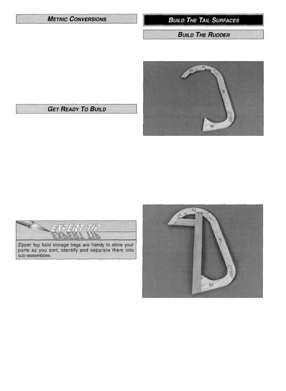
D 1. Place the die-cut 3/16" balsa rudder parts R2, R3, R4
and R5 over the plan in their locations. Check their fit and
sand the mating edges as needed. Use a T-bar or other flat
sanding block to make any necessary adjustments. Pin the
parts to the building board after proper alignment and fitting
has been done. Do not glue the parts together at this time.
D 2. Select the straightest piece from the four
3/16" x 5/8" x 18" balsa sticks. Set this piece aside for use
later on the stabilizer trailing edge.
D 3. Cut the rudder LE from another 3/16" x 5/8" x 18"
balsa stick. Fit the LE into the notch in R3 and against the
edge of R5. Cut the horizontal frame section from the
3/16" x 5/8" x 18" left over from the rudder leading edge,
and fit it in position. Pin the LE and horizontal frame section
in place and glue all the parts together with thin CA. Wipe
off any excess glue from the surface before it cures.
NOTE: Leave all the parts pinned to the building board.
7