Great Planes Piper J-3 Cub 20 Kit - GPMA0158 User Manual
Page 29
D 2. Use a straightedge to mark a line on the fuselage
sides where the stringers are to be located, taking
measurements from the plans.
D 6. Temporarily pin a stringer to the fuselage side and
position the previously constructed pushrod exit on the
stringer centered on the pushrod. Glue the pushrod exit to
the stringer but not to the fuselage. Build a pushrod exit
for the other side.
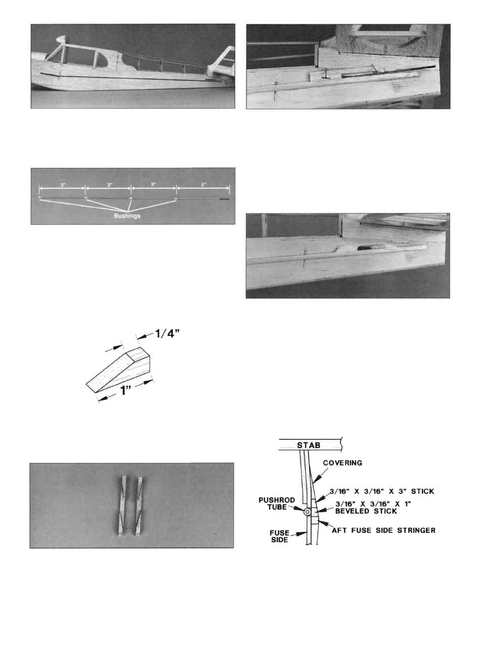
D 3. Cut eight 1/4" long bushings from the plastic inner
pushrod tube provided in the kit. Cut two 36" wire
pushrods 25" long, measured from the threaded end. Slide
four bushings on each wire pushrod, spacing them about
3" apart starting five inches from the threaded end. If the
bushings are loose, put a drop of CA on the wire at each
bushing to hold it in place. Install the pushrods in the tube,
but not until you are sure the CA has cured.
D1 7. Remove the stringer/pushrod exit from the fuselage
and round the outer corners of the stringer so it will
resemble a "tube." Sand the bevel at the rear of the long
stringer and the front of the short stringer. Glue the front
and rear stringers to the fuselage along the line you
previously marked.
D 4. From the remaining 3/16" balsa stick, cut four 1"
pieces and two 3" pieces. On each of the four 1" pieces,
make a mark 1/4" from one end and cut a bevel as shown
in the sketch.
D 5. Glue two diagonally cut sticks on each 3" stick.
Note: Be sure to make a right and a left side. These
pushrod exits will support the covering around
the pushrods.
D 8. Sand the pushrod exit to the same angle that will be
formed by the covering when stretched from the stringer to
the fuse side under the stabilizer.
29