Great Planes Piper J-3 Cub 20 Kit - GPMA0158 User Manual
Page 10
D 4 Trial fit but do not glue the tail gear wire in the rudder.
Make adjustments if necessary.
D 5 Temporarily pin the elevators on the plan Lay the
3/32" elevator joiner wire in place on the elevators and
mark its outline using a soft leaded pencil NOTE: Mark the
elevator joiner wire outline very lightly so that it can be
sanded off easily
D 10 Sand the leading edges of the stabilizer and fin and
the trailing edges of the elevator and rudder to a rounded
shape, as shown in the cross-section on the plan.
We have found that it's much simpler to do all hinging
after the model is covered.
D 1 Build one wing "half" or panel at a time You may want
to cut out each wing panel from the plan sheet to place on
your building board Tape the plan to your flat building
board and cover it with waxed paper Begin with the right
wing panel.
TWO WARPED SPARS INSTALLED
THIS WAY WILL RESULT IN A
STRAIGHT WING
D 6 Accurately drill a 1/16" diameter pilot hole
approximately 3/4" deep and perpendicular (90°) to the LE,
at each location Then drill the final hole with a 7/64" drill bit
to a depth of 7/8" (The hole is drilled slightly oversize to
allow for positioning, and to allow room to create a hard
epoxy "sleeve" around the wire).
D 7 Use your sharpened 1/8" diameter brass tube to cut a
groove in the leading edge of both elevators to accept the
elevator joiner wire Slightly round the inside corner where
the groove meets the hole to allow for the bend in the
elevator joiner wire.
TWO WARPED SPARS INSTALLED
THIS WAY WILL RESULT IN A
WARPED WING
D 8. Test fit (do not glue yet) the joiner wire into both
elevators Position the elevators against a straightedge to
check for straightness of the LE with the joiner wire
installed If the leading edges don't match up with the
straightedge, you may slightly enlarge the holes drilled in
the elevator leading edges Make sure both elevators are
flat on the work surface If both elevators do not lie flat, you
can make slight adjustments by twisting the joiner wire.
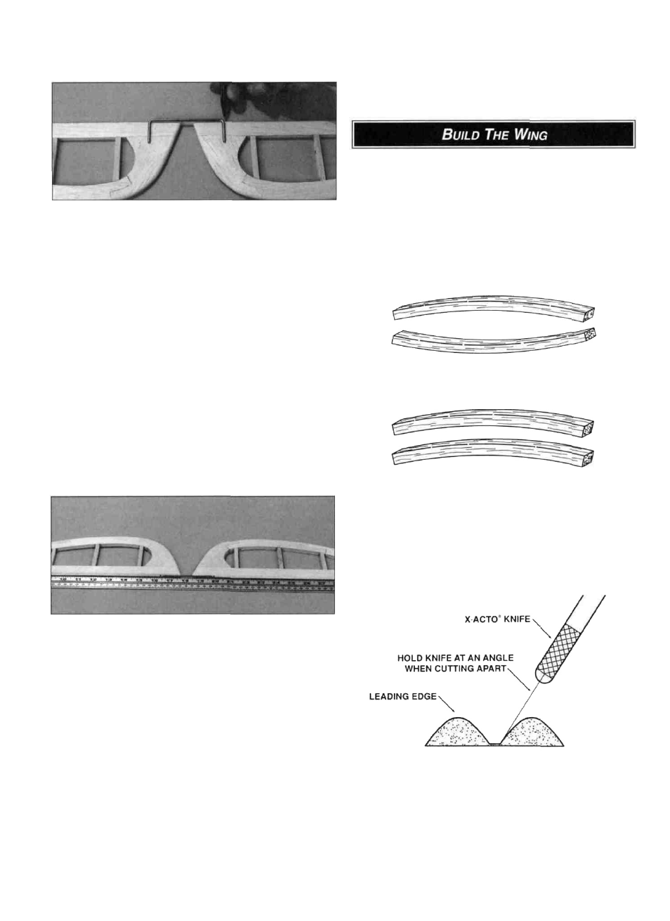
D 2. Locate all four 1/4" x 5/16" x 27" balsa spars and
examine them carefully for possible imperfections Look for
knots, soft spots, diagonal grain and any other
imperfections If possible, position each spar so the
imperfections are on the outer half of the wing panel
(toward the tip), where they will be least affected by high
stress If the spars are warped slightly try to "balance them
out" by installing the warped spars in opposite directions
(see sketch above).
D 9. Carve or sand the bevel on the leading edges of the
elevator and rudder A razor plane allows you to rough-in
the bevel before finishing with a sanding block Refer to the
plan for the correct angle
D 3. The shaped and notched wing leading edges (LE)
and trailing edges (TE) are fastened together by thin strips
of balsa Separate them by cutting with a hobby knife, as
shown in the sketch above
10