Great Planes Piper J-3 Cub 20 Kit - GPMA0158 User Manual
Page 13
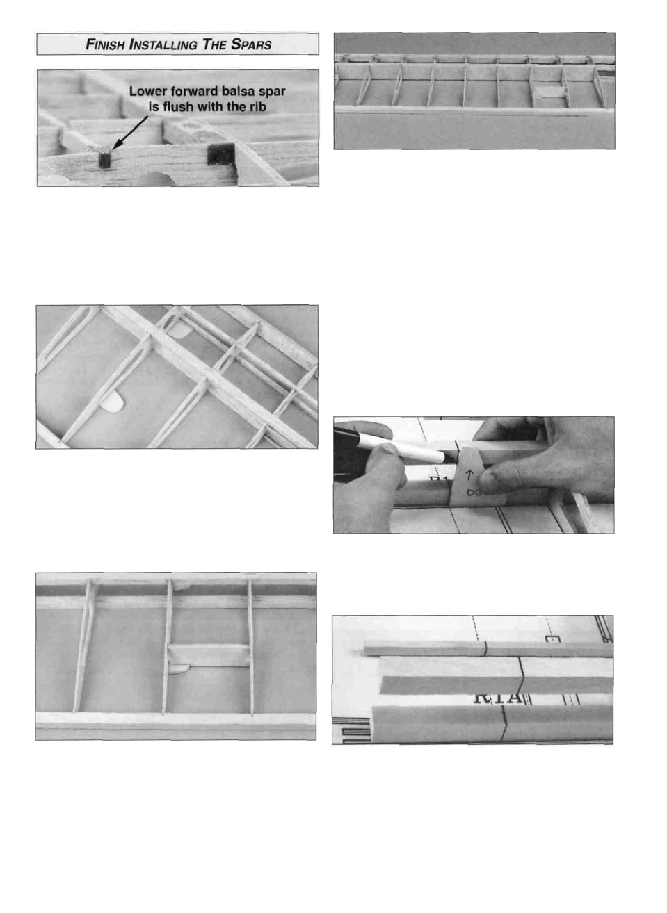
D D 1. Carefully remove the wing from the building board.
Turn the wing upside down. Press the balsa lower forward
spar into the notches in the ribs. Note that the front edge of
the notches in ribs R4 and R5 is 1/16" below the aft edge of
the notch. The lower forward spar should be flush with the
front edge of the notch and flush with the edge of ribs R2
and R3. Glue in place with thin CA.
D D 2. Carefully remove the wing from the building board
and turn it right side up. Align the spars and ribs with the
plans and pin it back on the building board. Test fit the
die-cut 1/8" ply forward and aft strut mounting plates to
the wing at the locations shown on the plans. Glue them to
the wing with thin CA. Then use thick CA to form a
reinforcing fillet at the glue joint.
D D 4. Glue eight 1/16" x 2-3/8" x 1-3/16" balsa vertical
grain shear webs to the rear of the balsa main spars
starting between ribs R3 and R4 and ending between the
last two R4 ribs. Shear webs will be installed between ribs
R2 and R3 after the wing halves are joined. The shear
webs are provided slightly thinner than the wing so they
may be positioned without protruding above or below the
top and bottom spars. It is not necessary to glue the shear
webs to the ribs - but, it is important to glue the shear
webs securely to the spars.
Note: At this point the wing should still be pinned to the
work surface. Of course, we cannot add shear webs if the
crossed T-pins are in position so remove the T-pins as you
go. Then replace the T-pins through the sheer webs in
order to keep the wing flat on your building board - or, use
weights on top of the wing instead of the T-pins to hold the
wing flat as you glue the shear webs in position. You only
need to replace T-pins at every other rib bay.
D D 3. Test fit the die-cut 1/8" ply strut mounting plate
brace over the aft strut mounting plate. Make sure the
brace contacts the wing ribs and the strut mounting plate.
Glue the brace with thin CA, followed by a fillet of thick CA
on all three pieces.
D D 5. Locate the 1/8" die-cut plywood dihedral gauge
(DG). Hold the gauge next to the main spar with the corner
of the gauge at the wing centerline on the plan. Mark both
sides of the main spars using the (DG) as shown in
the photo.
D D 6. Connect both lines by drawing a line across the top
of each spar.
D D 7. Follow the same procedure for the forward spars
and TE.
13