Great Planes Piper J-3 Cub 20 Kit - GPMA0158 User Manual
Page 20
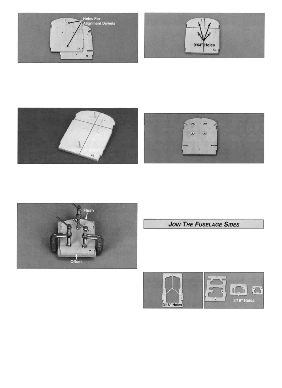
D 9 Remove any die-cutting irregularities from the die-cut
1/8" plywood firewall formers 1A and 1B Separately, drill
two 1/8" holes through the punch marks in each
firewall former
D 12 If you are going to use the engine mount supplied
with the kit, drill a 9/64" hole through the firewall at each of
the four punched locations for the 4-40 blind nuts If you
are using a different engine mount, draw horizontal and
vertical centerlines between the punch marks Center your
engine mount over these two lines, then mark and drill the
mounting holes for your alternate engine mount Notice that
the vertical "centerline" is offset to allow for the engine's
right thrust
D 10 Cut 1/2" from the end of two 1/8" x 15" turtle deck
dowels. Trial fit the two firewall formers together with the
alignment dowels in the holes Note: 1A is slightly shorter
than 1 B to allow for the angle of the bottom sheeting.
D 13 Lightly tap the 4-40 blind nuts into the holes from the
rear of the firewall Apply a drop of thin CA or 6-minute
epoxy around the flange of the blind nuts to secure them to
the firewall.
Note: the 1/8" die-cut formers are stamped only with the
necessary portion of their name For example, F2A is
stamped 2A
IMPORTANT: All formers must be installed with the
stamped identification number facing forward.
D 11 Use 30-minute epoxy to glue the formers together
with the alignment dowels inserted Refer to the note below.
Make sure all the punch marks and the embossed
numbers are facing the same direction. Cut the
alignment dowel flush with 1 A after the epoxy has cured
Note: If the firewall formers are warped, the assembly may
not flatten when clamped together To avoid a warped
firewall, clamp the two pieces to a flat table or other rigid,
flat board before the epoxy cures and remove excess
epoxy from the notches where other parts are to fit
D 1 Drill 3/16" holes at the punch marks in the die-cut 1/8"
plywood fuselage formers F2A, F3, F4 and F5
D 2 Test fit formers F2A, F3, F4 and F5 into the right
fuselage side Make adjustments if necessary Test fit the
same formers in the left fuselage side.
20