Great Planes Piper J-3 Cub 20 Kit - GPMA0158 User Manual
Page 41
plane, the receiver and battery can also be moved If this is
still not enough, nose weight may be easily installed by
using a heavy spinner hub or gluing lead weights into the
engine compartment Tail weight may be added by using
Great Planes (GPMQ4485) "stick-on" lead weight Later, if
the balance proves to be OK, you can open the fuse bottom
and glue these in permanently After the plane is properly
balanced, glue the servo tray in place with thick CA.
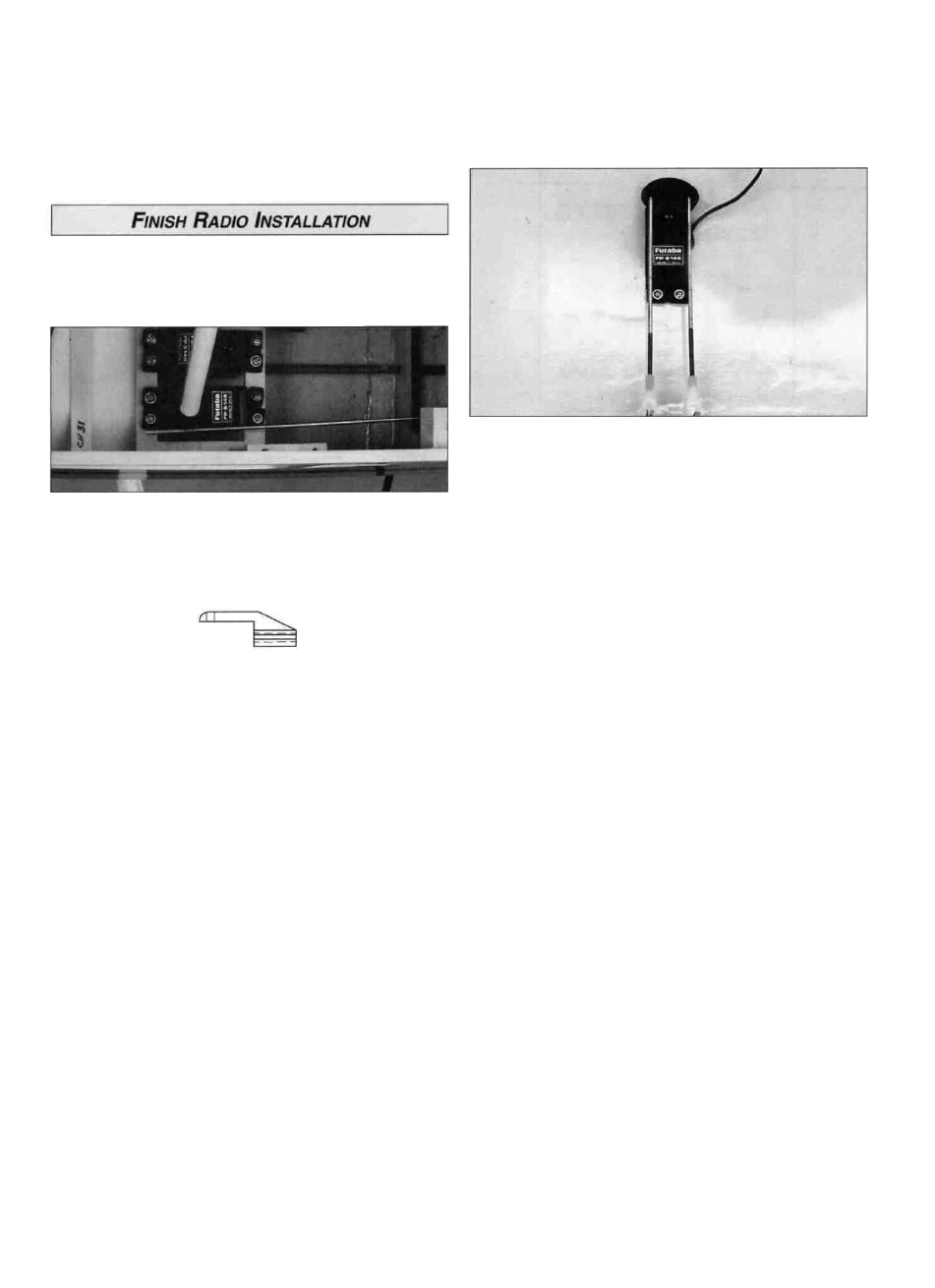
D 1 Turn on your transmitter and receiver, then center the
elevator and rudder servos. Be sure that the trim levers are
centered
D 2 Center the elevator, then mark the pushrod where it
crosses the outside servo horn hole. Enlarge the servo
horn hole with a 5/64" drill bit
D 3. Make a 90-degree bend in the pushrod on your mark,
then insert it through the enlarged hole in the servo horn.
Secure it with a nylon Faslink'".
Note: Do not shorten the antenna! Leave any excess
trailing behind the model.
D 7 Install two swivels on the aileron torque rods threaded
1/4" below the top edge of the aileron torque rod arms.
Screw a clevis 14 turns onto the threaded end of each 6"
wire pushrod Connect the clevises to the swivels and slide
a silicone clevis retainer over the clevis Plug the aileron
servo into the receiver Install a servo wheel setup for
differential throw (see the definition below) Switch on the
transmitter, then the receiver With the aileron servo
centered, hold the aileron pushrods on the servo wheel and
mark the hole locations on the pushrods Make a Z-bend at
the marks and insert the Z-bend in the servo wheel Install
the servo wheel on the servo and check the aileron throws
as shown below Lowering the swivels will cause the
ailerons to deflect more if you need more throw
D 4 Repeat steps 2 and 3 for the rudder.
* Differential Throw Ailerons that are set up to deflect more
in the upward direction than downward are said to have
" D i f f e r e n t i a l Throw." The purpose is to counteract
"Adverse Yaw."
D 5 Hookup the throttle using a brass screw lock
pushrod connector (not included) on the servo horn.
Make sure that the servo does not stall at either end of
its travel
D 6. Route the receiver antenna in one of the following ways:
a Insert the antenna into the "pushrod guide tube" and
tape it securely at the aft end.
b Route the antenna out the side of the fuselage just
under the TE of the wing Anchor the antenna to the top
of the fin with a rubber band.
* Adverse Yaw The tendency of an airplane to yaw in the
opposite direction of the roll For instance, when right
aileron is applied, the airplane yaws to the left, thus
opposing the turn Adverse yaw is common in trainer type
airplanes having flat-bottom wings, and is most noticeable
at slow speeds and high angles of attack, such as during
takeoffs and when stretching a landing approach Caused
by the unequal drag of the upward and downward
deflecting ailerons, this undesirable trait can be minimized
by setting up the ailerons with "Differential Throw," or by
"coordinating" the turns, using aileron and rudder
control simultaneously.
41