Great Planes Piper J-3 Cub 20 Kit - GPMA0158 User Manual
Page 23
D 5 Reinstall the LTF, TTF, cabin brace and the firewall
into the fuselage Practice clamping the fuselage sides
together around the firewall and tank floors, making sure
the firewall fits into its respective notches It may be
necessary to use hardwood sticks to evenly distribute the
force of the clamps on the fuselage sides Clamp the sticks
together with masking tape, lots of rubber bands or clamps
Once satisfied with the fit of all parts, glue them together
with 30-minute epoxy.
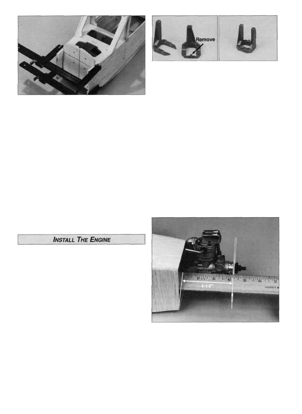
If you are using the included Great Planes adjustable
engine mount, cut or break the "spreader bar" from each
mount half Carefully trim any extra material left by the
spreader bar from each mount half The surfaces where the
spreader bars were attached must be smooth to allow the
mount halves to fit together Trim the flashing off any rough
edges if necessary Assemble the mount halves as shown.
Note: The procedures for mounting the 2-stroke and
4-stroke are the same.
D 6 While you still have an open, accessible structure,
inspect all glue Joints, making sure all formers, doublers,
tank floors and cabin brace are securely bonded Apply
fillets of medium or thick CA where required.
D 1. Attach the engine mount to the firewall using the
4 - 40 x 1" phillips head machine screws, # 4 washers
and lock washers provided.
D 7. Sand the tab on the cabin brace flush with the aft
side of former F2A.
Before we continue, now is the best time to fuelproof the
fuel tank compartment We recommend brushing on one of
the following 30-minute epoxy thinned with a little alcohol,
polyester resin, or fuelproof paint or dope We'll fuelproof
the exterior of the firewall/engine compartment later.
Also, you need to decide if you want your engine side
mounted or inverted Side mounting is recommended for
the 20- 26 4-stroke, but an inverted engine will allow you to
use two dummy engines on the cowl Mounting the 15-25
2-stroke inverted is recommended If you have elected to
use the Great Planes adjustable engine mount included in
the kit, you may easily mount the engine on its side or
inverted as the mounting holes are symmetrical This
allows repositioning the engine without drilling new engine
mounting holes in the firewall.
(Top and bottom sheeting shown in photo will be added later)
D 2 Install a straight piece of scrap plywood against the
drive washer on the engine Locate the engine on the
engine mount so the distance between the firewall and the
aft edge of the piece of scrap plywood is 4-1/8" (105mm).
Mark the mounting screw locations on the engine mount
(see the expert tip)
23