Great Planes Piper J-3 Cub 20 Kit - GPMA0158 User Manual
Page 24
How to accurately pinpoint the location of the engine
mounting bolt holes on a plastic engine mount.
A. Before positioning the engine on the engine mount,
apply a light coat of petroleum jelly on the mounting
lugs of the engine mount.
B. After the engine is in position, sprinkle talcum
powder or micro balloons down the mounting holes in
the flanges of the engine.
C. Carefully remove the engine. The hole locations
should have powder on them. Heat the point of a small
nail with a match or lighter. Quickly press the point into
the center of the hole locations marked with powder.
Mark all four holes with the hot point of the nail.
D 3. After marking the location of the holes, remove the
engine mount from the firewall and drill four 5/64" holes for
the #4 x 5/8" sheet metal screws.
(Top and bottom sheeting shown in photo will be added later.)
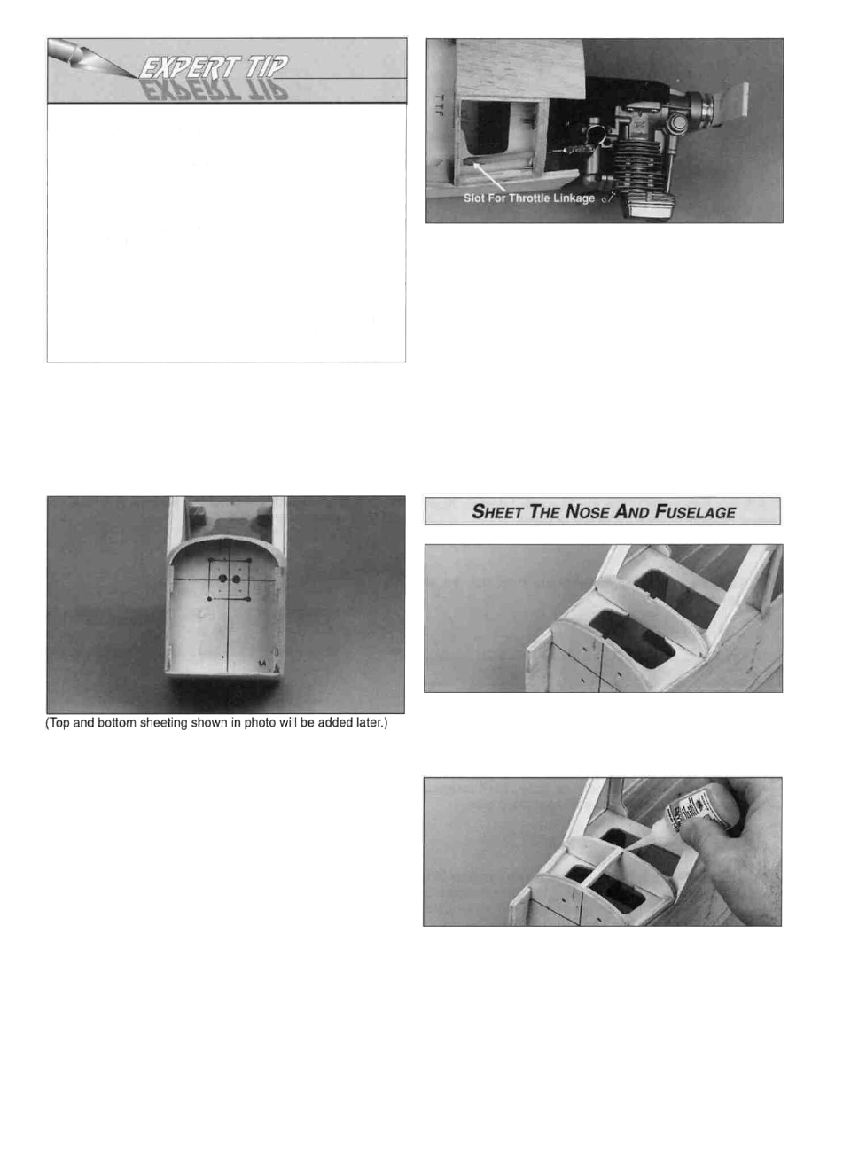
D 6. Remove the engine and drill the hole for the throttle
linkage. Temporarily install the fuel tank in the fuel tank
compartment. Be sure the throttle linkage will clear the side
of the fuel tank in the fuel tank compartment. If the O.S. .26
Surpass engine is used, a slot in the plywood TTF will need
to be drilled to allow the throttle linkage to pass through.
D 7. Roughen the outside surface of the Plastic guide
tubing for the throttle linkage with 150-grit sandpaper, then
insert it through the firewall, the TTF and former F2A. The
tube should extend into the radio compartment 2" behind
former F2A. Glue the tube into the fuselage with thick CA
and trim the tube flush with the firewall.
D 1. Glue the die-cut 1/8" plywood instrument panel
perpendicular to TTF with thick CA.
D 4. Before reinstalling the engine mount, draw four lines
connecting the center of the four blind nuts. For standard
medium size silicone fuel tubing, drill two 1/4" (15/64" for a
perfect fit) holes in the center of the square you just drew.
Set the engine on the engine mount and reinstall the
engine mount on the firewall, lining up the embossed marks
on the edges of the engine mount with the horizontal
centerline on the firewall. If the embossed marks are
separated, position them equally on both sides of
the centerline.
D 5. Set the engine on the engine mount and determine
the location of the throttle linkage. The throttle linkage is
not provided in this kit. We recommend using the Great
Planes Flexible Cable Pushrod (GPMQ3700).
D 2. Cut three stringers from one of the 3/16" x 3/16" x 30"
balsa sticks, to fit between the firewall and the instrument
panel. Refer to the cross-section on the fuselage plan for
the exact positioning of the two bottom stringers. Notice
they are slightly angled inward. Glue all three stringers in
position with medium CA.
24