Great Planes Piper J-3 Cub 20 Kit - GPMA0158 User Manual
Page 42
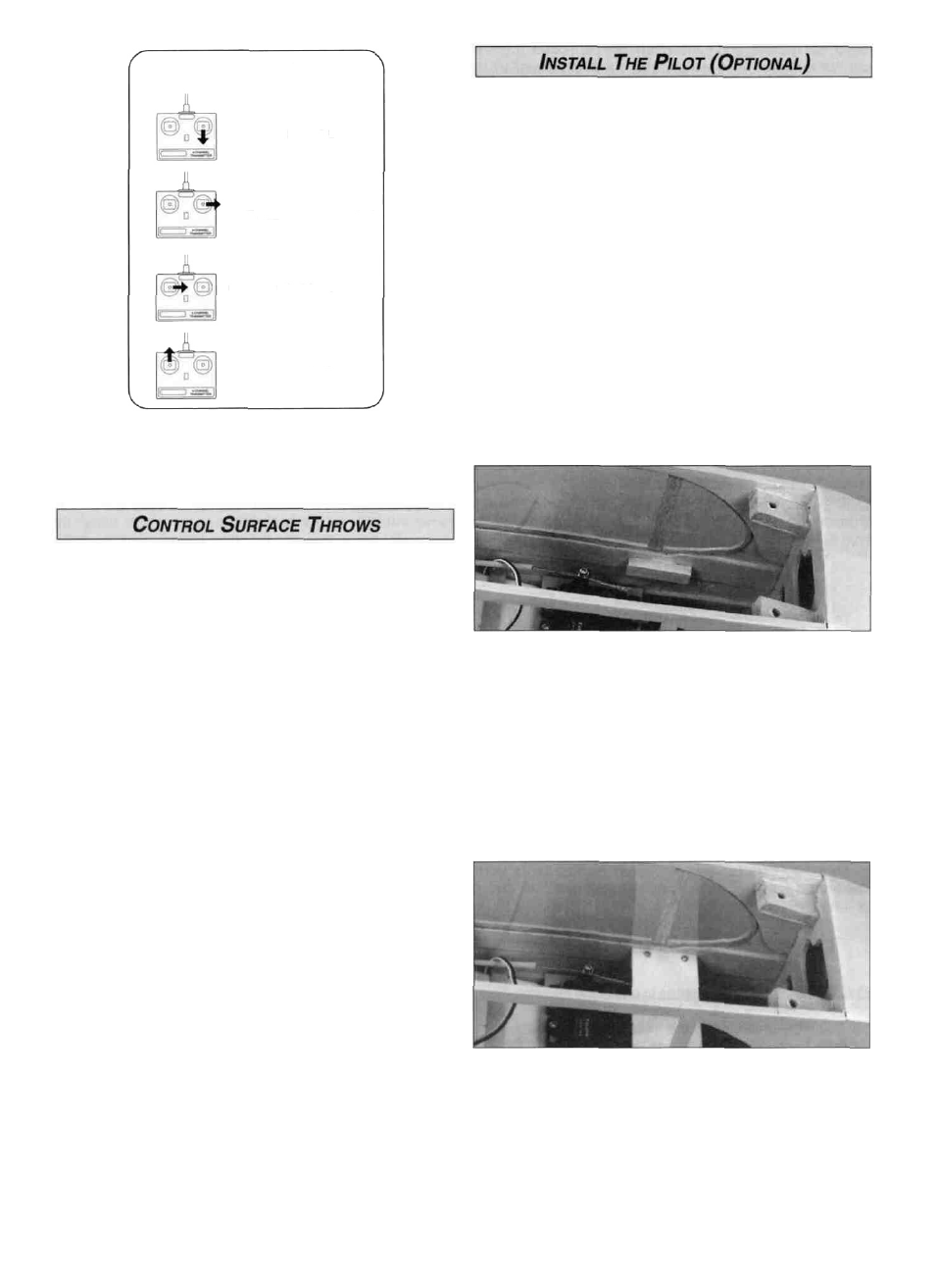
4-CHANNEL RADIO SETUP
(STANDARD MODE 2)
ELEVATOR MOVES UP
RIGHT AILERON MOVES UP
LEFT AILERON MOVES DOWN
RUDDER MOVES RIGHT
CARBURETOR WIDE OPEN
D 1. We used a 2" Williams Bros #184 Sportsman Pilot
with 1/4" cut off the base to allow the pilot's head to clear
the aileron pushrods. Assemble your pilot and paint it
as desired.
D 2. Cut two pieces of scrap 3/16" x 3/16" hard balsa
1-1/2" long. For a shelf to support the pilot, cut one piece of
scrap 1/8" plywood 1-1/2" wide to fit between the fuselage
sides, centered between the rear window braces. Drill two
3/32" holes at each end of the 1/8" plywood (see the photo
for step 4 for the approximate location). In J-3 Cubs, the
pilot would fly from the rear seat when flying solo.
D 8. Turn on the radio system and check the direction of all
control functions. They must all move in the direction
shown in the sketch. If not, change the position of the
reversing switches on your transmitter.
NOTE: Throws are measured at the widest part of the
elevators, rudder, and ailerons. Hold a ruler vertically on
your workbench or block it up on books to perform
these measurements.
SINGLE RATE TRANSMITTER
The following throws are for a transmitter that does not
have Dual Rates.
ELEVATOR:
1/2" up
1-3/8" right
7/16" up
1/2" down
1-3/8" left
5/16" down
RUDDER:
AILERONS:
DUAL RATE TRANSMITTER
"Dual Rate" is a feature on some radios which allows
you to switch the control surface throws in flight. This
lets you change the responsiveness of your model with
regard to the maneuvers you are doing.
The following throws are for a transmitter equipped for
"Dual Rate" servo control.
(High Rate)
5/8" up
5/8" down
ELEVATOR:
(Low Rate)
3/8" up
3/8" down
1-3/8" right
1-3/8" left
3/8" up
1/4" down
1-3/8" right
1-3/8" left
RUDDER:
7/16" up
5/16" down
AILERONS:
NOTE: The balance and surface throws for this aircraft have
been extensively tested. We are confident that they represent
the settings at which the Cub 20 flies best. Please set up your
aircraft to the specifications listed above. If, after a few flights,
you would like to adjust the throws to suit your taste, that's
fine. Too much throw can force the plane into a stall or snap
roll, so remember, "more is not better."
D 3. Tack glue or pin the two 3/16" square balsa pieces
1/4" below the top edge of the top fuselage doublers on
each side of the fuselage, centered between the rear
window braces. The top edge of the balsa pieces must be
1/8" above the elevator and rudder pushrods. Place the
1/8" plywood shelf on the 3/16" balsa pieces and mark the
four holes on the balsa pieces.
D 4. Remove the plywood shelf and the 3/16" balsa pieces.
Drill a 1/16" hole at each mark. Thread #2 x 3/8" sheet
metal screws (not included) into the 1/16" holes. Remove
the screws and place a drop of thin CA into each hole to
harden the balsa.
42