Great Planes Learjet 40 Kit - GPMA0439 User Manual
Page 36
D 1 Assemble and install an eight ounce fuel tank
according to the manufacturer's instructions.
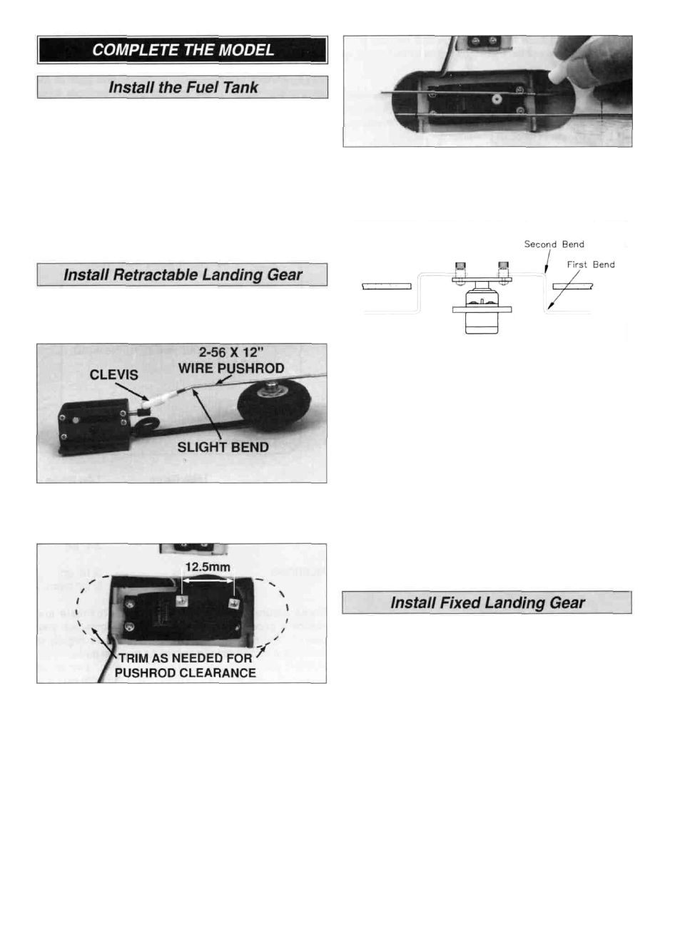
D 2 Install the tank by placing it on a piece of 1/4" foam
rubber on the tank floor, then securing it in position
with rubber bands.
D 3 Route the supply and pressure tubes to the engine and
muffler pressure tap Be sure there are no kinks in the tubes
Perform steps 1 thru 7 if installing retracts. Skip this
section if installing fixed gear.
D 4.Pull the retract pushrods to the stops This will lock
the gear in the down position Mark the pushrod about
1/8" short of the servo case Make a 90 degree bend in
the pushrods, out and away from the surface of the wing.
D 1 Assemble the retract pushrods with the materials
specified at the front of this manual Temporarily install your
retract servo (Futaba 135G low profile servo recommended)
D 2. A large round servo horn with holes drilled 12 5mm
from the center is suitable for most retract actuation
Install screw-lock pushrod connectors (not included,
GPMQ3870 recommended) onto the horn as shown
Install the servo horn on the servo, then mount the servo
in the wing
D 3 Connect the pushrods to the retracts, then insert
the pushrods through the clearance holes toward the
servo. Mount the retracts with #4 x 1/2" sheet metal
screws (not included).
D 5 Make another bend in each pushrod about 5/16"
above the first, to point the pushrod ends toward the
pushrod connectors on the servo
D 6 Hook up and cycle the retracts a few times to make
sure that there is no interference or binding in the
linkage Make minor adjustments as required Trim off the
excess pushrod wire at the servo once satisfied with the
retracts operation NOTE: 4-40 set screws should be
substituted for the socket head cap screws supplied with
the screw-lock pushrod connector.
D 7 Install and hook up the nose wheel retract as you
did during construction, then connect the steering cable
to the steering arm with a metal clevis.
D 1 Insert the torque rod portion of the main wire landing
gear (the shorter end) into the LG blocks in the bottom of
the wings Use the straps and plan as guides, then drill
1/16" pilot holes for the screws Attach the gear legs with
two nylon landing gear straps and four #2 x 3/8" sheet
metal screws per gear.
D 2 Refer to the cross section of the firewall on the plan,
then install the nose gear using the supplied 5/32' wheel
collar and set screw and the nylon steering arm/wheel
collar assembly Install a screw-lock pushrod connector
upside down in the last hole of the steering arm securing it
with a locking washer Connect the steering arm to the
braided wire steering cable and secure it with a 4-40 x 1/8"
cap screw
36