Great Planes Learjet 40 Kit - GPMA0439 User Manual
Page 34
will result in a cleaner hole than if you use a slower speed
power or hand drill Drilling the hole will twist some of the
wood fibers into the slot, making it difficult to insert the
hinge, so you should reinsert the knife blade, working it
back and forth a few times to clean out the slot.
D 6 Install the control horns on both elevators and rudder
in the location shown on the fuse plan Mark the mounting
holes, then drill through the control surface with a 3/32" bit
at each mark Apply a couple of drops of thin CA into each
hole to strengthen them When the CA has cured, mount all
of the horns using 2-56 x 1/2" machine screws
C Insert the hinges and install the control surface Verify
the left-right positioning of the control surface, and close
up the hinge gap to 1/32" or less It is best to leave a
very slight hinge gap, rather than closing it up tight, to
help prevent the CA from wicking along the hinge line
Make sure the control surface will deflect to the
recommended throws without binding If you have cut
your hinge slots too deep, the hinges may slide in too far,
leaving only a small portion of the hinge in the control
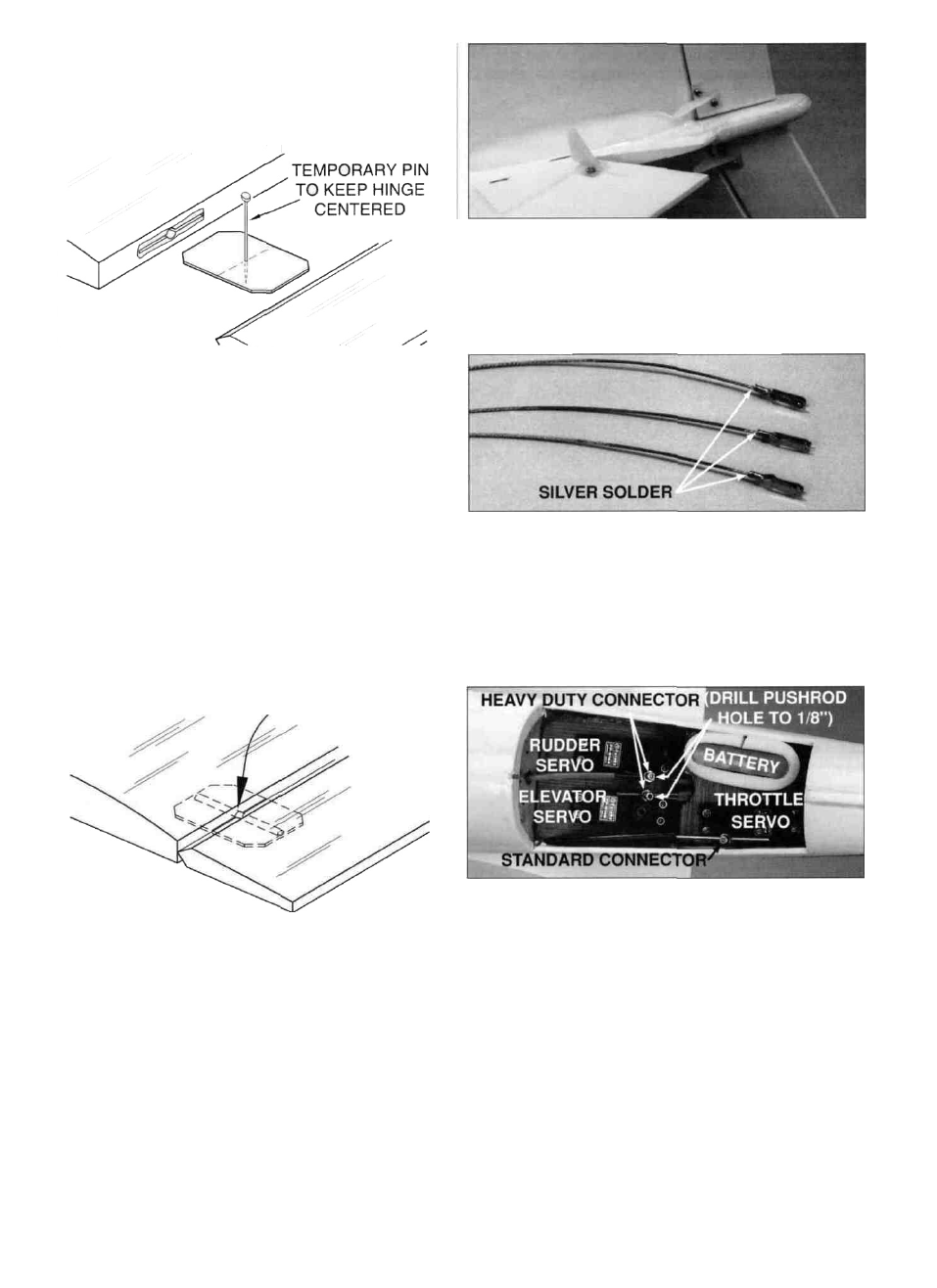
surface To avoid this, you may insert a small pin
through the center of each hinge, before installing This
pin will keep the hinge centered while installing the
control surface Remove the pins before proceeding
D 7 Cut three pieces of braided cable to 18" long Use
silver solder (GPMR8070) to solder a metal clevis to one end
of each cable If installing retracts, solder an additional
metal clevis (not included, GPMQ3810) to one end of a 36"
cable This cable will be used for the nose wheel steering.
NOTE: Because of the acidic nature of the flux, you must
thoroughly clean each joint after soldering to avoid
destructive corrosion Lightly oil the cable after cleaning
ASSEMBLE THEN APPLY 6 DROPS
OF THIN CA TO CENTER
OF HINGE, ON BOTH SIDES
D 4 Apply 6 drops of thin CA adhesive to both sides of
each hinge on the elevators and rudder only - not the
ailerons yet. Allow a few seconds between drops for the
CA to wick into the slot Note that the small "tunnels" you
created by drilling the 3/32" holes allow the CA to freely
travel in to the entire surface of the hinge, producing an
extremely secure bond.
D 5. Pack each of the torque rod holes in the ailerons with
30-minute epoxy (a toothpick works well for this), then
install the ailerons with their hinges Repeat the gluing
technique described in step 9 and allow the epoxy to cure
REFER TO THIS PHOTO FOR THE NEXT 6 STEPS
D 8 Drill through the pushrod hole of both heavy duty
screw lock pushrod connectors with a 1/8" drill bit Install
the connectors on the rudder and elevator servo horns but
don't install the locking washer until after the control throws
are adjusted Install the horns on the servos Install a
standard screw-lock pushrod connector on the throttle
servo horn. Once again, don't use the locking washer
D 9 Slide a silicone clevis retainer onto each clevis, then
insert the rudder and elevator cables into their guide tubes
from the control surface end Thread them into the
connectors on the servos. Both of the elevator cables fit
into one hole.
34