Great Planes Learjet 40 Kit - GPMA0439 User Manual
Page 20
d 5. After referring to the fuselage plan, drill the
pushrod guide tube holes at each of the punch marks on all
of the formers. Use a 1/8" drill bit for the nosewheel
steering guide tube and a 3/16" bit for the outer throttle
guide tube.
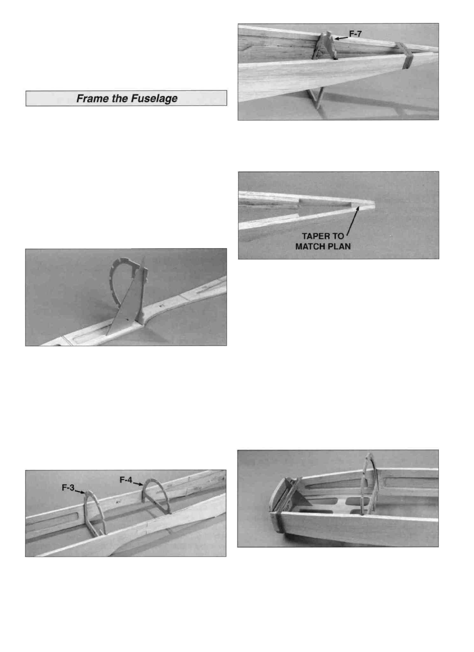
NOTE: Do not drill any holes in F-7 at this time.
(Assembles right side-up over the plan)
Note: The firewall is lower than the bottom of the fuselage
sides, so in order to install it at the proper time, the
fuselage must be built with the nose extending beyond
the left side of your building board. Pin the fuselage top
view plan to the board, with F-1 extending about an inch
past the edge of the board.
Important: Unless specified differently, all fuselage formers
are made from die-cut 1/8" plywood. Be sure that the die
stamped numbers on each former face the nose of the
model or the pushrod routing holes will not line up.
D 1. With the right fuselage side held flat on your building
board, glue F-3 in place, perpendicular to the fuselage side.
Be careful, when installing all of the fuselage formers, that
you position them correctly (see plan).
D 2. Turn this assembly upright and pin F-3 in its proper
location over the plan, then glue the left fuselage side to
F-3. NOTE: All formers have a centerline embossed on the
bottom end. Use these marks to align the formers over the
fuse plan.
D 3. Glue F-4 in place between the fuselage sides. Be
sure to seat F-4 all the way to the top of the "long" notch.
D 4. Pull the rear of the fuselage sides together and hold
them with rubber bands. Glue F-7 into place and pin the
support leg on the bottom of F-7 to the board, again making
sure that the former is centered over the plan.
D 5. Cut a 1" length from the 1/4" x 3/4" balsa left over
from the fin frame. Taper it to a wedge shape to fit between
the fuse sides at the aft end of the fuse. Remove the rubber
bands holding the rear of the fuselage sides together and
place the wedge between the sides. Measure carefully
with a 90 degree triangle to be sure the aft ends of the
sides are directly above the centerline shown on the plan,
then glue the wedge in place with thin CA. Trim the top and
bottom of the wedge flush with the fuse.
D 6. Glue in formers F-6 and then F-5, centered over the
plan and pinned to the board. Pin the fuselage sides to the
board at F-5.
D 7. Hold the front of the fuselage sides together with
rubber bands while you glue F-2 in place. Slide the die-cut
1/8" ply tank floor into position with the embossed letters
pointing toward the top of the fuse. Glue the tank floor to
F-2 only - not to the fuse sides. (See next photo.)
D 8. Fit the firewall assembly between the front of the
fuselage sides. Sand an angle on the edges of the firewall
to match the angle of the fuselage sides when they are
20