Great Planes Learjet 40 Kit - GPMA0439 User Manual
Page 26
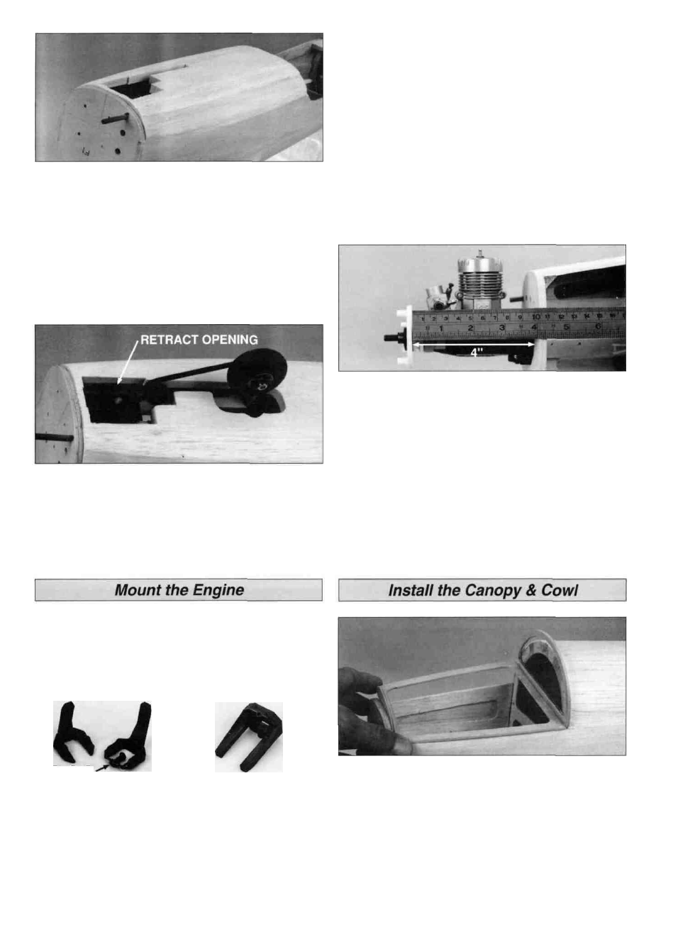
D 40. Remove the retract mechanism. Trim and sand the
tops of the F-8s flush with the top of F-1 D, F-2A and F-3A,
then glue the 1/2" x 4" x 13" balsa front bottom block in
place. If you are using retracts, cut a clearance hole for the
retract mechanism in the block. HINT: To locate the position
of the retract mechanism, push a sharpened piece of wire
through the retract screw holes in the tank floor out through
the bottom of the block. Align the retract mechanism over
the holes, then mark its shape. Carve off the overhanging
portions of the fuse bottom and roughly create the
rounded shape.
D 41. If you are using retracts, reinstall the retract unit,
axle and wheel. Slowly retract the gear while you cut away
the portions of the bottom block which interfere. A template
has been provided on the fuse plan for reference. Cycle the
retract a few times to be sure that everything works
correctly, then remove the retract assembly.
bars were attached must be smooth to allow the mount
halves to fit together. Trim the flashing from any rough
edges if necessary. Assemble the mount halves as shown.
D 2. Temporarily install the engine mount on the firewall
using four #4 flat washers and four 4-40 x 1" machine
screws. Don't tighten the screws completely until after the
engine has been positioned.
D 3. Position the engine on the engine mount. Slide the
engine mount halves apart until the engine mounting lugs
will sit flat on the rails. Adjust the mount up and down until
the tic marks on the mount are centered on the horizontal
reference line on the firewall. After adjusting the mount,
tighten the 4-40 screws to hold it firmly in position.
D 4. Position the engine so that the backplate of a spinner
will be 4" (102mm) in front of the firewall. Carefully mark
the engine mounting holes on the rails with a sharpened
piece of wire or a pencil lead.
D 5. Remove the engine and engine mount from the fuse.
Use a centerpunch or sharpened nail to "dimple" the marks
on the rails, then drill a 7/64" hole through the rails at each
punch mark. If you have access to a drill press, this is the
best tool for the job. However, if you are using a hand held
electric drill, try to keep the bit perpendicular to the rails.
Test fit the engine but don't screw it permanently in position
just yet.
The Great Planes adjustable engine mount is simple and
convenient to use. It may be used to mount most .20 - .40
two-stroke and .26 - .48 four-stroke engines. Nose gear
bearings for 5/32" diameter wire are incorporated in the
mount.
REMOVE
D 1. Cut or break the "spreader bar" from each mount half.
Carefully trim any extra material left by the spreader bar
from each mount half as the surface where the spreader
D 1. Protect the edges of the fuse and formers with waxed
paper, then fit the die-cut 1/8" ply canopy base between F-
1 and F-2. Glue the die-cut 1/8" ply C-1 and C-2 to the
canopy base using F-1 and F-2 to set the proper angles. Be
careful not to glue the canopy base to the fuselage.
26