Great Planes Learjet 40 Kit - GPMA0439 User Manual
Page 23
servo tray in place between F-6 and F-7. NOTE: Don't block
the pushrod holes in F-6 with the servo tray. The rear servo
tray must be glued to the top edge of the aft doubler and not
to the stringers.
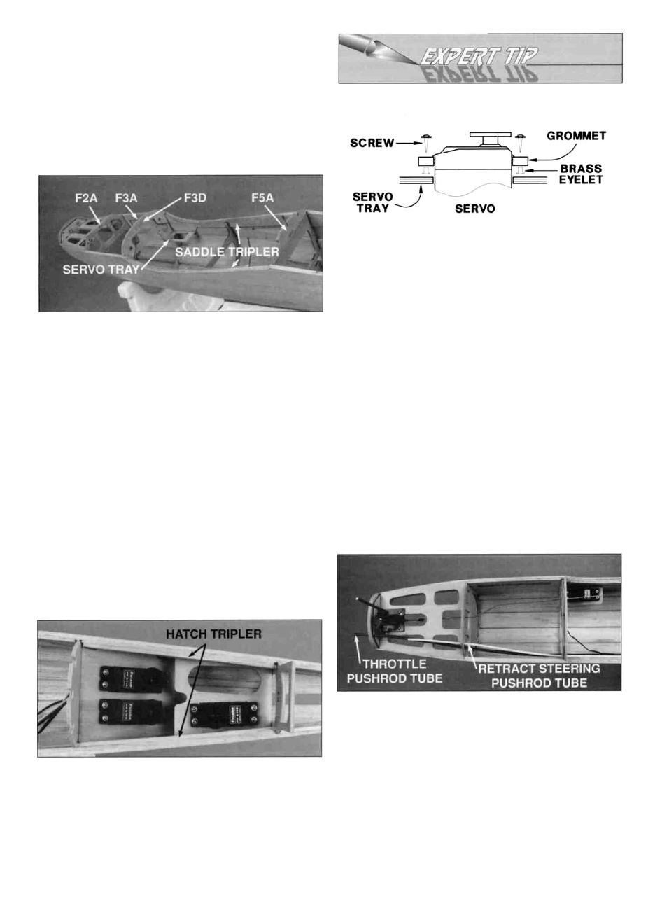
MOUNTING SERVOS
D 22. Glue the die-cut 1/8" balsa wing saddle triplers in
place. If you are using retracts, install the die-cut 1/8"
plywood nose retract servo tray.
The proper way to mount a servo is as follows:
A. Insert a rubber grommet into each of the four
servo notches.
B. Insert a metal eyelet from the bottom side of the rubber
grommet. This way the wide portion of the eyelet will be
in contact with the servo tray when mounted.
C. Test fit the servo in the tray, and enlarge the openings
so the servo will not touch the tray. The rubber
grommets will isolate the servo from the hard vibration
of the airplane's structure.
D. Position the servo, then mark the location of the
mounting holes. Drill pilot holes with a 1/16" bit at
each mark.
E. Use the servo screws supplied with your radio to mount
the servo(s) in the servo tray. Tighten the screws until
they just touch the top of the metal eyelet.
D 23. Glue F-2A to the bottom of F-2. Be sure the control
cable tube holes are on the right side. Glue F-3A to the
bottom of F-3 and then glue F-3D to rear of F-3 and F-3A.
Glue F-5A to the bottom of F-5.
D 25. Install the retractable nose gear if you will be using
one. Follow the routing on the plan to install the 3/16 OD
throttle and 1/8" OD nosewheel steering guide tubes.
Insert the cable and flexible pushrod, then check to see
that there is no binding. When everything is working
smoothly, glue the tubes in place at each former.
D 24. Cut and fit the 1/8 x 1/4 x 6-1/4" balsa hatch triplers
to the fuselage sides along the hatch opening. With
reference to the plan, install all of the fuselage servos and
the forward control pushrods. (See Expert Tip that follows.)
D 26. If you are using retracts, make the retract pushrod
from 2-56 threaded pushrod wire (not included,
GPMQ3716) and a nylon clevis. Install an adjustable 5/32"
axle on the gear strut as shown on the plan and install the
nosewheel with two 5/32" wheel collars (not included,
GPMQ4150). Hook up the steering cable and the retract
pushrod, then install the retract servo and cycle the retract
to be sure everything is working properly. Remove the gear
strut but leave the retract mechanism in place.
23