EVCO EPK4LHX Hardware manual User Manual
Page 15
EVCO S.p.A.
c-pro 3 NODE kilo | Hardware manual ver. 1.0 | Code 114CP3NKE104
page 15 of 44
ETHERNET
Ethernet MODBUS TCP port
Please see paragraph 6 "CONFIGURATION" for the settings of the Ethernet MODBUS TCP port.
4.3
Insertion of the termination resistor of the CAN CANBUS port
To reduce reflections on the signal transmitted through the cables connecting the devices to a CAN network it is necessary to insert the
termination resistor of the first and last elements of the network.
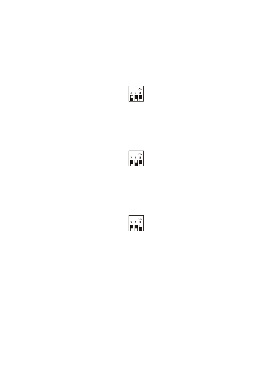
To insert the termination resistor, place the micro-switch 3 in the ON position.
4.4
Insertion of the RS-485 MODBUS master/slave port termination resistor
To reduce reflections on the signal transmitted through the cables connecting the devices to a RS-485 network it is necessary to insert
the termination resistor of the first and last elements of the network.
To insert the termination resistor, place the micro-switch 2 in the ON position.
4.5
Insertion of the RS-485 MODBUS slave port termination resistor
To reduce reflections on the signal transmitted through the cables connecting the devices to a RS-485 network it is necessary to insert
the termination resistor of the first and last elements of the network.
To insert the termination resistor, place the micro-switch 1 in the ON position.
4.6
RS-485 MODBUS master/slave port polarisation
The devices can polarise the RS-485 MODBUS master/slave port; the polarisation can be set through the configuration parameter.
4.7
RS-485 MODBUS slave port polarisation
The devices cannot polarise the RS-485 MODBUS slave port; the polarisation must be carried out by another device.