Single pole single throw – Kenmore 808353 User Manual
Page 86
Attention! The text in this document has been recognized automatically. To view the original document, you can use the "Original mode".
Power Miser Circuits - Single Pole Single Throw
The healer Is controlled by cam switch B-3 during the washes and rinses, and by cam switch B-7 durmg the dry as
shown in Figure 94. If the “Power Miser" switch is open, the heater circuit is interrupted during the dry period
SINGLE POLE SINGLE THROW
ORANGE BUS
PORTION OF
TIMER
f i g u r e
9 4
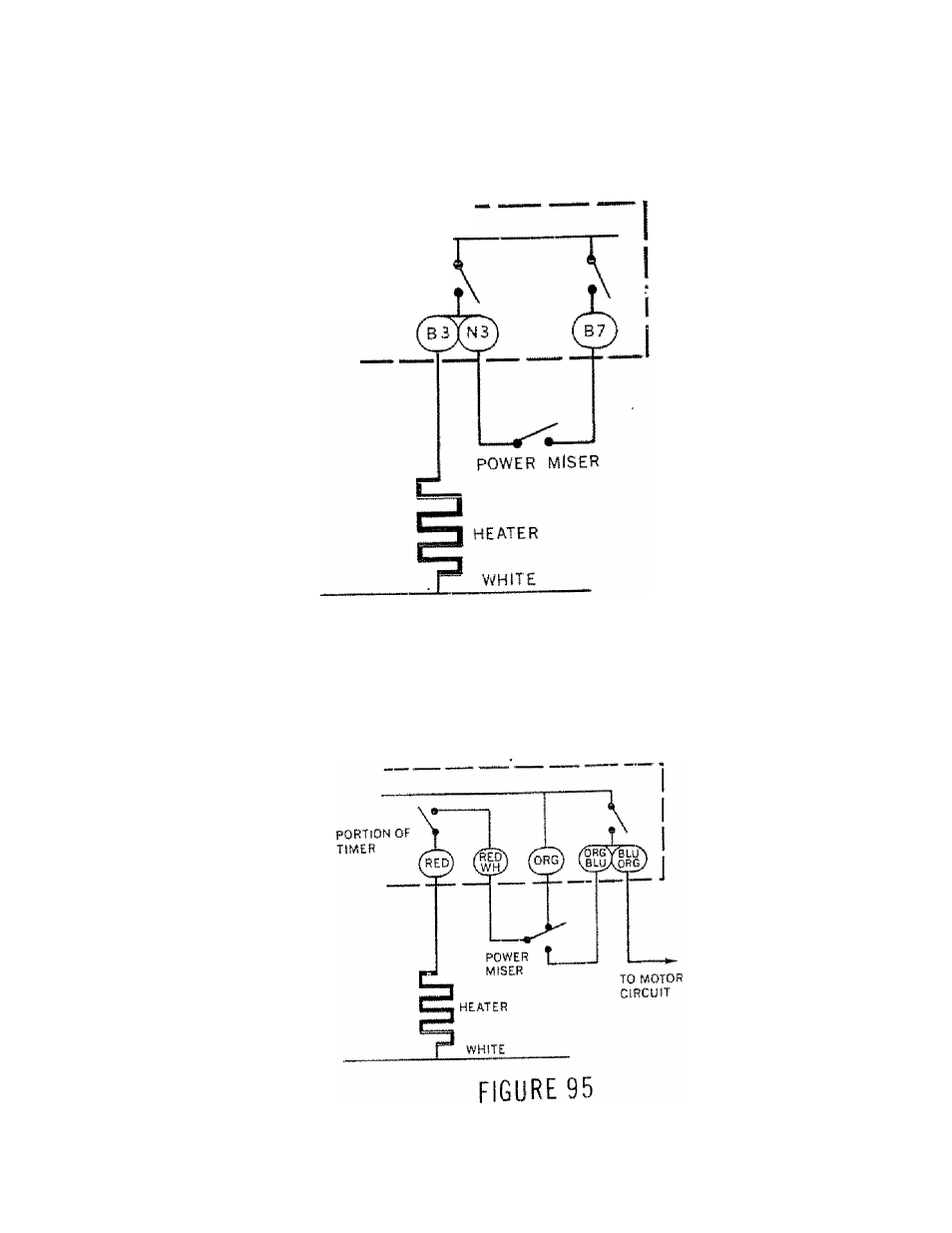
F Power Miser Circuits ~ Single Pole Double Throw Switch
The heat is
controlled
primarily by the “Red" cam switch. When the "Orange" P^wer miser
"Red" cam switch energizes the healer whenever it is closed. However, if the power miser is closed to ORG-BLUE
the “Red cam ^Scan only energize the heater when the motor circuit is closed (washes and rinses only). (See
Figure 95)
SiNGLE POLE DOUBLE THROW
8 3