Figure 30a – Kenmore 808353 User Manual
Page 31
Attention! The text in this document has been recognized automatically. To view the original document, you can use the "Original mode".
2 SEAL
SCREW
1 PUMP HOUSIMG
LOWER
RING CLAMPS
SHIMS
FIGURE 30A
SCREW
WASHER
UPPER IMPELLER
MACERATOR BLADE 5
SPACER PLATE
SHROUD 4
PUMP PLATE
PUMP GASKET
□"
ring
LOWER IMPELLER 3
PUMP GASKET
NUT
WASHER
PUMP HOUSING
UPPER
SCREW
FAN SLINGER
BAFFLE
PLATE
n8"MODELS3^.'^
ONLY
B.
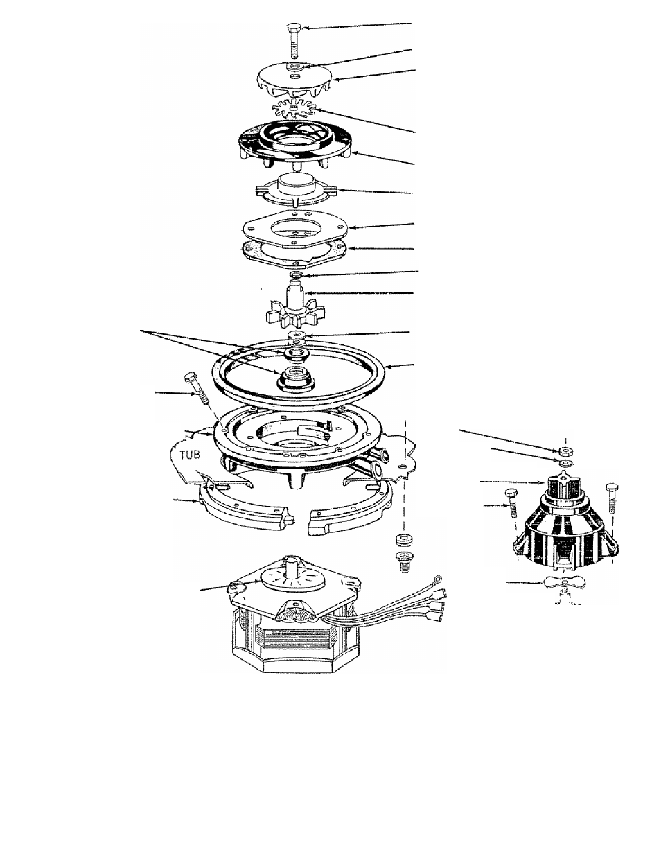
Pump Assembly
The pump assembly consists of the following components (Refer to
F i g u r e 3 0 A D
1, Pump housing or casting which consists of an upper and lower part It attaches directly to the main motor and
the tub,
The upper housing directs water from the upper impeller into the spray arm
2
Shaft Seal-
Provides a water light sea! which prevents water from leaking from he pump housing at the rriotor
shaft, The seal consists of two parts. The rubber mounted carbon seal is seated into the pump housing and the
rubber mounted ceramic sea! fits into the lower impeiier.
2 9