ALTANA Haze-Gloss Manual User Manual
Page 9
Gardn
er
haze-g
loss
Gardn
er
BYK
Garde
ner
Versio
n: 2
.6
Copyr
ight 1
990
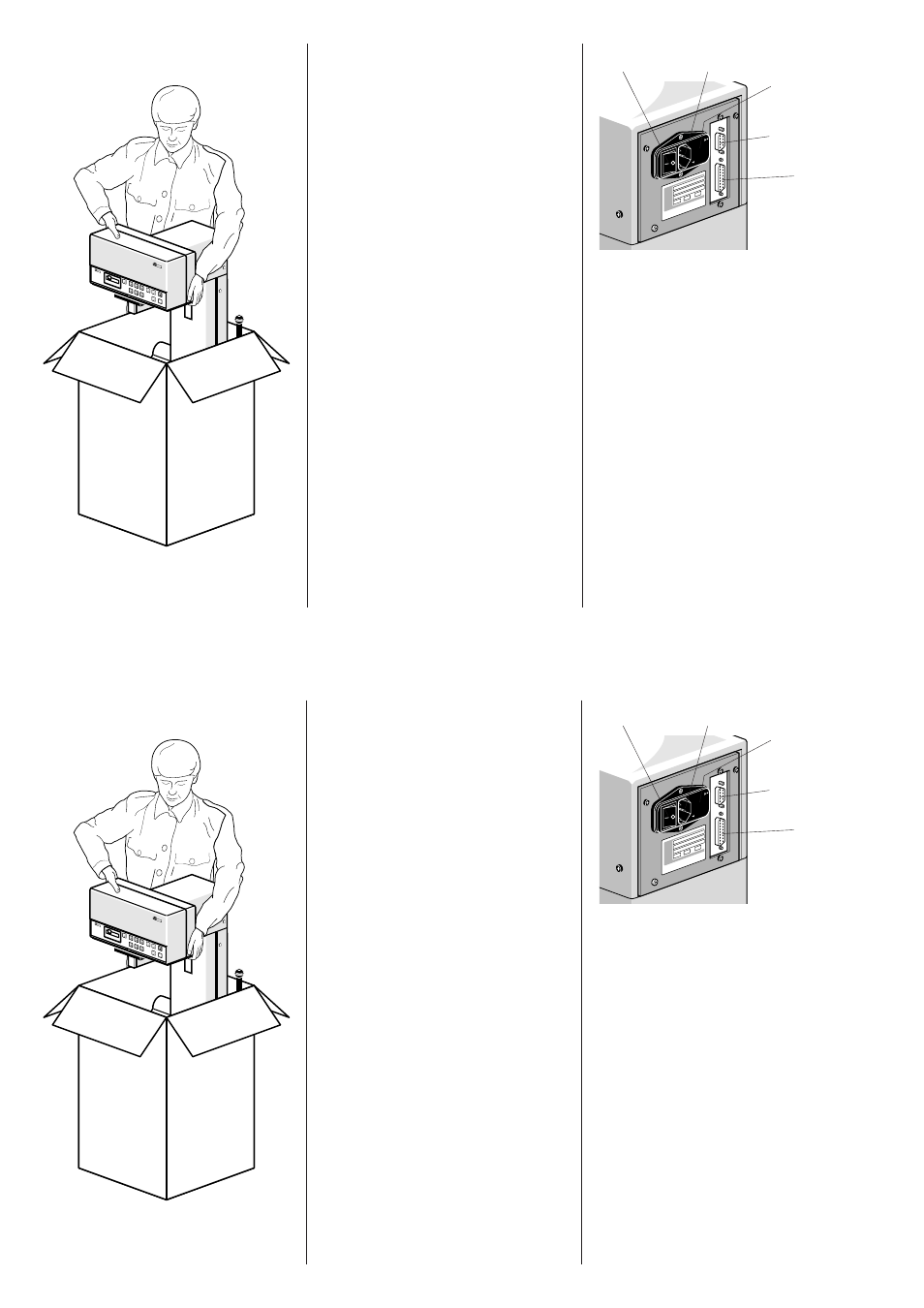
Footswitch
RS 232 Interface
Voltage Selector
Fuses
Jack for Power Cord
Power Switch
TYP
CAT.-NR.
F-NR.
4601
9017571
110/220
V
50/60
HZ
250
VA
BYK
-GA
RDE
NER
GM
BH
LAU
SIT
ZER
ST
R. 8
819
2 G
ERE
TSR
IED
2
TEL
EFO
N (0
817
1) 4
93-0
TEL
EX
5 27
851
TEL
EFA
X (0
871
) 49
3-40
U
S
E
O
N
L
Y
W
IT
H
2
5
0
V
F
U
S
E
S
/
E
M
P
L
O
Y
E
R
U
N
IQ
U
E
M
E
N
T
A
V
E
C
D
E
S
F
U
IB
L
E
S
W
IT
H
2
5
0
V
110-120 V
220-240 V
Installation
Always disconnect the instrument from
the mains supply before you plug-in or
unplug the various connectors!
Unpack the instrument and check for
any possibility of shipping damage
(visual inspection). Before initial
operation, check if the delivery is
complete (for the components see
Chapter 12, Ordering Guide ).
Install the unit at its place of destination.
Check the position of the voltage
selector switch on the back panel and, if
necessary, set the switch to your power
requirements as follows: Remove the
plastic cover next to the mains cord
jack. Then plug-in the plastic cover so
that the triangular marking on the power
switch housing and the required voltage
range indication coincide.
With the unit being still disconnected,
plug the power cord into the shockproof
socket. In the case of motorized units:
connect the footswitch.
If required, plug the PC connection
cable into the RS 232 jack.
Gardn
er
haze-g
loss
Gardn
er
BYK
Garde
ner
Versio
n: 2
.6
Copyr
ight 1
990
Footswitch
RS 232 Interface
Voltage Selector
Fuses
Jack for Power Cord
Power Switch
TYP
CAT.-NR.
F-NR.
4601
9017571
110/220
V
50/60
HZ
250
VA
BYK
-GA
RDE
NER
GM
BH
LAU
SIT
ZER
ST
R. 8
819
2 G
ERE
TSR
IED
2
TEL
EFO
N (0
817
1) 4
93-0
TEL
EX
5 27
851
TEL
EFA
X (0
871
) 49
3-40
U
S
E
O
N
L
Y
W
IT
H
2
5
0
V
F
U
S
E
S
/
E
M
P
L
O
Y
E
R
U
N
IQ
U
E
M
E
N
T
A
V
E
C
D
E
S
F
U
IB
L
E
S
W
IT
H
2
5
0
V
110-120 V
220-240 V
Installation
Always disconnect the instrument from
the mains supply before you plug-in or
unplug the various connectors!
Unpack the instrument and check for
any possibility of shipping damage
(visual inspection). Before initial
operation, check if the delivery is
complete (for the components see
Chapter 12, Ordering Guide ).
Install the unit at its place of destination.
Check the position of the voltage
selector switch on the back panel and, if
necessary, set the switch to your power
requirements as follows: Remove the
plastic cover next to the mains cord
jack. Then plug-in the plastic cover so
that the triangular marking on the power
switch housing and the required voltage
range indication coincide.
With the unit being still disconnected,
plug the power cord into the shockproof
socket. In the case of motorized units:
connect the footswitch.
If required, plug the PC connection
cable into the RS 232 jack.