AERCO Belimo F7...HD/HDU Series Valve User Manual
Page 40
800-543-9038 USA
866-805-7089 CANADA
203-791-8396 LATIN AMERICA
40
0
7/10 - Subject to change. © Belimo Air
controls (USA), Inc.
FLANGE BOLTING RECOMMENDATIONS
Lug Valves, 2”-30”, ANSI 125/150 Bolt Pattern
Valve Size
Thread Size
Number Required
Bolt Length Semi-Lug Butterfl y (inches)
2”
5/8-11
4
1.25
2-1/2”
5/8-11
4
1.50
3”
5/8-11
4
1.50
4”
5/8-11
8
1.75
5”
3/4-10
8
1.75
6”
3/4-10
8
2.00
8”
3/4-10
8
2.25
10”
7/8-9
12
2.25
12”
7/8-9
12
2.50
14”
1-8
12
2.75
16”
1-8
16
2.75
18”
1 1/8-7
16
3.50
20”
1 1/8-7
20
4.25
24”
1 1/4-7
20
4.75
30”
1 1/4-7
24
4.50
PRE-INSTALLATION PROCEDURE
1. Remove any protective fl ange covers from the valve.
2. Inspect the valve to be certain the waterway is free from dirt and
foreign matter. Be certain the adjoining pipeline is free from any
foreign material such as rust and pipe scale or welding slag that
could damage the seat and disc sealing surfaces.
3. Any actuator should be mounted on the valve prior to installation to
facilitate proper alignment of the disc in the valve seat.
4. Check the valve identifi cation tag for materials, and operating
pressure to be sure they are correct for the application.
Installation Recommendations
F6…HD(U), F7…HD(U) Series Butterfl y Valves
FLANGE BOLTING RECOMMENDATIONS
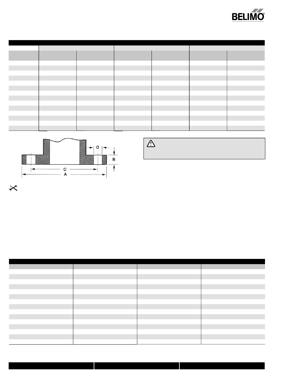
Flange Detail for ANSI B16.5 Pipe Flanges
FLANGES
DRILLING
BOLTING
Nominal
Pipe Size
A
Flange Diameter
B
Flange Thickness
C
Diameter of
Bolt Circle
D
Diameter of
Bolt Holes
Number
of Bolts
Diameter
of Bolts
2”
6”
3/4”
4-3/4”
3/4”
4
5/8”
2-1/2”
7”
7/8”
5-1/2”
3/4”
4
5/8”
3”
7-1/2”
15/16”
6”
3/4”
4
5/8”
4”
9”
15/16”
7-1/2”
3/4”
8
5/8”
5”
10”
15/16”
8-1/2”
7/8”
8
3/4”
6”
11”
1”
9-1/2”
7/8”
8
3/4”
8”
13-1/2”
1-1/8”
11-3/4”
7/8”
8
3/4”
10”
16”
1-3/16”
14-1/4”
1”
12
7/8”
12”
19”
1-1/4”
17”
1”
12
7/8”
14”
21”
1-3/8”
18-3/4”
1-1/8”
12
1”
16”
23-1/2”
1-7/16”
21-1/4”
1-1/8”
16
1”
18”
25”
1-5/8”
22-3/4”
1-1/4”
16
1-1/8”
20”
27-1/2”
1-11/16”
25”
1-1/4”
20
1-1/8”
24”
32”
1-7/8
29-1/2”
1-3/8”
20
1-1/4”
WARNING! Personal injury or property damage may result
if the valve is installed where service conditions could exceed the
valve ratings.
5. Check the fl ange bolts or studs for proper size, threading, and length.
6. These valves are designed to be installed between ASME/ANSI Class
125/150 fl anges.
7. Carefully follow installation using welded fl anges on page 82 of
this document.
8. Follow ASME fl ange alignment standards:
SECTION 335.1.1 ALIGNMENT
a. PIPING DISTORTIONS: Any distortion of piping to bring into
alignment for joint assembly which introduces a detrimental strain
in equipment or piping components is prohibited.
b. FLANGE JOINTS: Before bolting up, fl ange faces shall be aligned
to the design plane within 1/16”/ft measured across any diameter;
fl ange bolt holes shall be aligned within 1/8” maximum offset.
9. When observed during assembly, the fl ange faces shall be parallel
within 1 degree, and the force required to align pipe axes shall not
exceed 10 lb/ft per inch of NF bolts and nuts shall be fully engaged.