Af actuators, multi-function technology, Warning live electrical components – AERCO Belimo F7...HD/HDU Series Valve User Manual
Page 25
800-543-9038 USA
866-805-7089 CANADA
203-791-8396 LATIN AMERICA
25
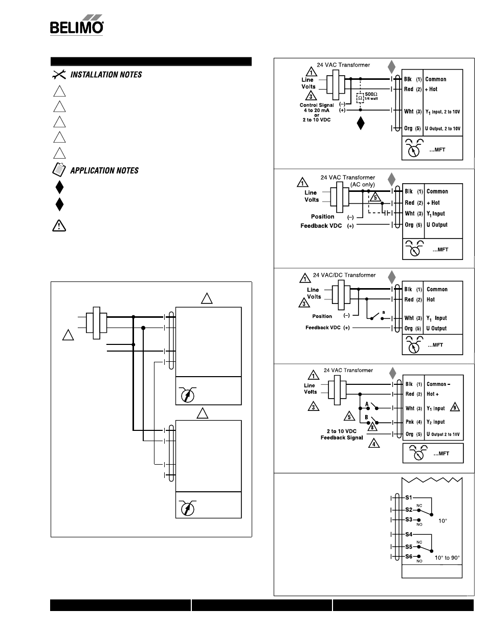
Wiring Diagrams
3
Actuators may also be powered by 24 VDC.
4
IN4004 or IN4007 diode (IN4007 supplied, Belimo part number
40155).
5
Triac A and B can also be contact closures.
6
Control signal may be pulsed from either the Hot (Source) or
Common (Sink) 24 VAC line.
7
Position feedback cannot be used with Triac sink controller.
The actuators internal common reference is not compatible.
The ZG-R01 500
Ω resistor converts the 4 to 20 mA control signal to
2 to 10 VDC, up to 2 actuators may be connected in parallel.
Meets cULus or UL and CSA requirements without the
need of an electrical ground connection.
WARNING Live Electrical Components!
During installation, testing, servicing and troubleshooting of this product, it may
be necessary to work with live electrical components. Have a qualifi ed licensed electrician
or other individual who has been properly trained in handling live electrical components
perform these tasks. Failure to follow all electrical safety precautions when exposed to live
electrical components could result in death or serious injury.
AF Actuators, Multi-Function Technology
W399_Butter
fly
VDC/4-20 mA
W399_Butter
fly
PWM
M
W
399_Butter
fl
y
On/Off control
Off
l
W
399_Butter
fl
y
Floating Point control
AFB24-MFT-S
AFX24-MFT-S
Auxiliary Switches for AFX24-MFT-S-X1
W
600_
AFB
_
AFX
1
AFX24-MFT-S-X1
1
Blk (1) Common
Red (2) + Hot
Wht (3) Y
Input, 2 to 10 V
Org
(5) U
Output 2 to 10 V
CCW CW
Master
CCW CW
Slave
24 VAC Transformer
Line
Volts
Control Signal
2 to 10 VDC
(–)
(+)
3
5
Blk (1) Common
Red (2) + Hot
Wht (3) Y
Input, 2 to 10 V
Org
(5) U
5
Master
_S
la
ve
Master/Slave
0
7/10 - Subject to change. © Belimo Air
controls
(USA
), Inc
.