Af actuators, on/off, Caution equipment damage, Warning live electrical components – AERCO Belimo F7...HD/HDU Series Valve User Manual
Page 23
800-543-9038 USA
866-805-7089 CANADA
203-791-8396 LATIN AMERICA
23
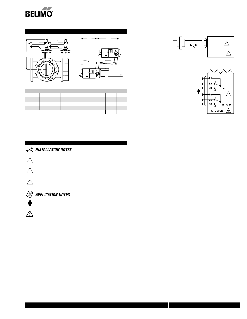
Wiring Diagrams
2
CAUTION Equipment damage!
Actuators may be connected in parallel.
Power consumption must be observed.
3
Actuators may also be powered by 24 VDC.
4
For end position indication, interlock control, fan startup, etc., AF24-S
US incorporates two built-in auxiliary switches: 2 x SPDT, 7A (2.5A)
@ 250 VAC, UL listed, one switch is fi xed at +5°, one is adjustable 25°
to 85°.
Meets cULus or UL and CSA requirements without the
need of an electrical ground connection.
WARNING Live Electrical Components!
During installation, testing, servicing and troubleshooting of this product, it may
be necessary to work with live electrical components. Have a qualifi ed licensed electrician
or other individual who has been properly trained in handling live electrical components
perform these tasks. Failure to follow all electrical safety precautions when exposed to live
electrical components could result in death or serious injury.
AF Actuators, On/Off
1 Common
2 + Hot
2
24 VAC Transformer
AF24 US
Line
Volts
3
p
j y
W
1
94
On/Off Wiring
W195-A
U
X
Auxiliary Switches
Dimensions with 3-Way Valve
10
10
D
A
B
C
Dimensions (Inches)
Fail Safe (psi)
Valve
Size
A
B
C
D(Max)
BHC
AF
2*AF
F750HD
2”
4.50
6.15
6.15
15.50
4.75
200
F750HDU
2”
4.50
6.15
6.15
15.50
4.75
50
F765HD
2½”
5.00
6.76
6.76
16.00
5.50
200
F765HDU
2½”
5.00
6.76
6.76
16.00
5.50
50
F780HDU
3”
5.50
7.28
7.28
16.25
6.00
50
HS
DW
G
P11
0
7/10 - Subject to change. © Belimo Air
controls
(USA
), Inc
.