Syx-p interface wiring detail, Potentiometer (factory pre-set), Dip switch settings – AERCO Belimo F7...HD/HDU Series Valve User Manual
Page 12: Warning
800-543-9038 USA
866-805-7089 CANADA
203-791-8396 LATIN AMERICA
12
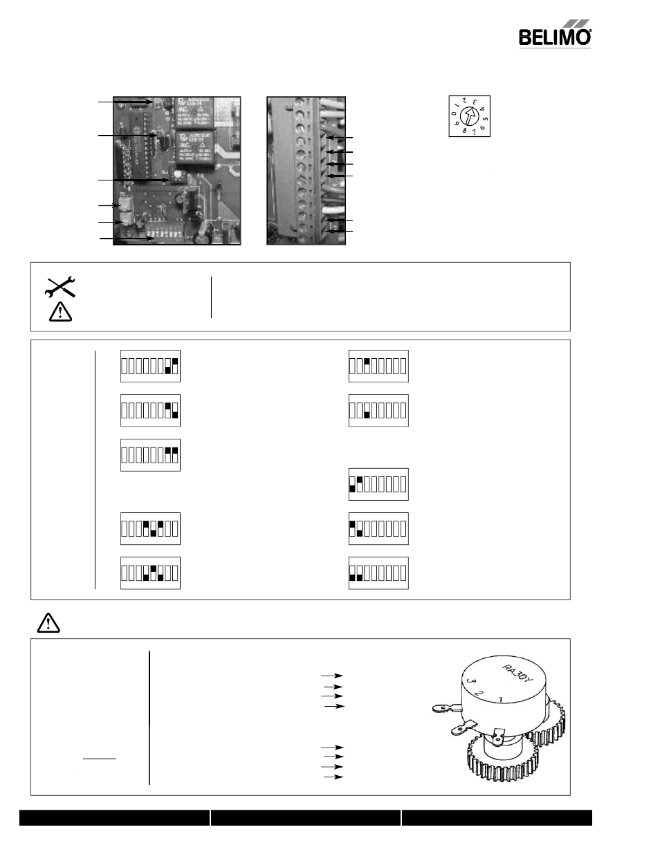
SYx-P Interface Wiring Detail
Potentiometer
(Factory Pre-set)
For 2-position actuators with 1k feedback option
Potentiometer points 1, 2, 3 are wired to terminal blocks 8, 9,, 10.
When a valve is closed:
8, 9
1k
7
9, 10
0k
7
When a valve is opened:
8, 9
0k
7
9, 10
1k
7
For modulating actuators with 1k feedback option*
Potentiometer points 1, 2, 3 are wired to terminal blocks 8, 9,, 10.
When a valve is closed:
8, 9
1k
7
9, 10
0k
7
When a valve is opened:
8, 9
0k
7
9, 10
1k
7
INPUT = 2-10 VDC
INPUT = 4-20mA
INPUT = 1-5 VDC
OUTPUT = 2-10 VDC
OUTPUT = 4-20mA
LOSS OF SIGNAL = STOP
RESPONSE = REVERSE
RESPONSE = DIRECT
LOSS OF SIGNAL = CLOSED
(Direct Acting)
LOSS OF SIGNAL = OPEN
(Reverse Acting)
LOSS OF SIGNAL = OPEN
(Direct Acting)
LOSS OF SIGNAL = CLOSED
(Reverse Acting)
ON
ON
OFF
ON
OFF
OFF
OFF
OFF
ON
ON
ON
ON
OFF
OFF
OFF
OFF
ON
ON
OFF
ON
1
2
3
4
5
6
7
8
6
7
8
2
3
5 4
1
8 7 6
2
5
3
4
1
8 7 6
2
5
3
4
1
8 7 6
2
5
3
4
1
6
7
8
2
3
5 4
1
8 7 6
2
4
5
3
1
7
8
5
6
4
2
3
1
8 7 6
2
4
5
3
1
8 7 6
2
4
5
3
1
Notes:
1.
Do not change sensitivity or dip switch settings with power applied!
2.
VR1 and VR2 are factory calibrated and should not be moved.
3.
Motor CAMS have been factory calibrated and should not be moved.
Dip
Switch
Settings
Sensitivity switchsetting
is position #3 for factory
default. To
T
T widen dead-
band, select a higher
number (up to 9).
N
Supply
H
- SIG
+ IN
- FB
+ OUT
Open LED
Closed LED
Sensitivity
VR2
VR1
Dip Switch
WARNING
*On modulating
actuators DO NOT
master/
rr slave using
optional potentiometer.
INSTALLATION NOTES
CAUTION
4.
Applicable to the SY1 and legacy SY2-12 actuators.
0
7/10 - Subject to change. © Belimo Air
controls (USA), Inc.