Gkb24-3-x1 actuators, on/off, floating point, Warning live electrical components! g, On/off control off l – AERCO Belimo F7...HD/HDU Series Valve User Manual
Page 27: Floating point control, Wiring diagrams, Actuators may also be powered by 24 vdc
800-543-9038 USA
866-805-7089 CANADA
203-791-8396 LATIN AMERICA
27
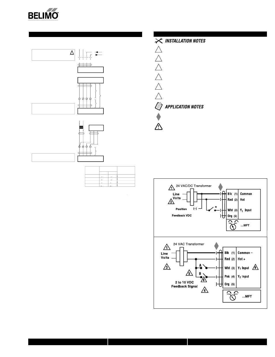
GKB24-3-X1 Actuators, On/Off, Floating Point
W
399_10
On/Off control
Off
l
W399_10
Floating Point control
Wiring Diagrams
1
Provide overload protection and disconnect as required.
3
Actuators may also be powered by 24 VDC.
4
Position feedback cannot be used with Triac sink controller.
The actuator internal common reference is not compatible.
5
Control signal may be pulsed from either the Hot (source)
or the Common (sink) 24 VAC line.
8
Contact closures A & B also can be triacs.
A & B should both be closed for triac source and open for triac sink.
9
For triac sink the common connection from the actuator
must be connected to the hot connection of the controller.
Meets UL requirements without the need of an electrical ground
connection.
WARNING Live Electrical Components!
G
During installation, testing, servicing and troubleshooting of this product, it
may be necessary to work with live electrical components. Have a qualifi ed
licensed electrician or other individual who has been properly trained in
handling live electrical components perform these tasks. Failure to follow all
electrical safety precautions when exposed to live electrical components could
result in death or serious injury.
NOTE: Wiring diagrams shown are for single actuator
mounted solutions
Electrical Installation
Wiring diagram
Y
U
1
3
2
5
– +
T
~
Cable colors:
1 = black
2 = red
3 = white
5 = orange
Cable lengths
Y
U
1
3
2
5
T
~
A
C
L
1
L
2
L
tot
A
= Actuator
C
= Control unit
L
1
= Belimo connecting cable, 1 m (4 x 0.75 mm
2
)
L
2
= Customer cable
L
tot
= Maximum cable length
Cross section
L
2
T
/
~
Max. cable length
L
tot
=
t
L
1
+ L
2
Example for DC
AC
DC
0.75 mm
2
<30 m
<5 m
1 m (L
1
) + 4 m (L
2
)
1.00 mm
2
<40 m
<8 m
1 m (L
1
) + 7 m (L
2
)
1.50 mm
2
<70 m
<12 m
1 m (L
1
) + 11 m (L
2
)
2.50 mm
2
<100 m
<20 m
1 m (L
1
) + 19 m (L
2
)
L
N
Y
U
T
1
3
2
5
A
C
A
AC
A 24 V
V
V
AC
C
C 230 V
V
L
1
A
= Actuator
C
= Control unit
L
1
= Belimo connecting cable, 1 m (4 x 0.75 mm
2
m
m )
Note
• Connect via safety isolation transformer.
• Parallel connection of other actuators possible.
Note performance data for supply.
!
DC 0 ... 10 V
DC 2 ... 10 V
Note
When several actuators are connected in parallel,
the maximum cable length must be divided by the
number of actuators.
Note
There are no special restrictions on installation if
the supply and data cable are routed separately.
0
7/10 - Subject to change. © Belimo Air
controls
(USA
), Inc
.