BUCHI Encapsulator B-395 Pro User Manual
Page 25
5 Putting into operation
25
B-395 Pro
Operation Manual, Version C
5.4.1.2 Electrode
3
2
4
5
6
1
a Screw nut M10 (polyamide)
O-Ring (10.82×1.78)
Insulator
Electrode
Connecting piece
Screw M4×12
Figure 5-8: Electrode with connecting elements
The electrode is attached with either the elongated ring showing downwards or upwards so that
the distance between the nozzle and the electrode can be varied. The short distance between the
nozzle and the electrode is recommended during the production of small beads and if solutions of low
viscosity are used. The long distance is recommended during the production of large beads (approxi-
mately > 800 µm). The separation of the bead from the liquid jet should happen inside of the ring of
the electrode, where the electrostatic field is highest, or secondarily, in the space between the elec-
trode and the nozzle, depending on the properties of your material.
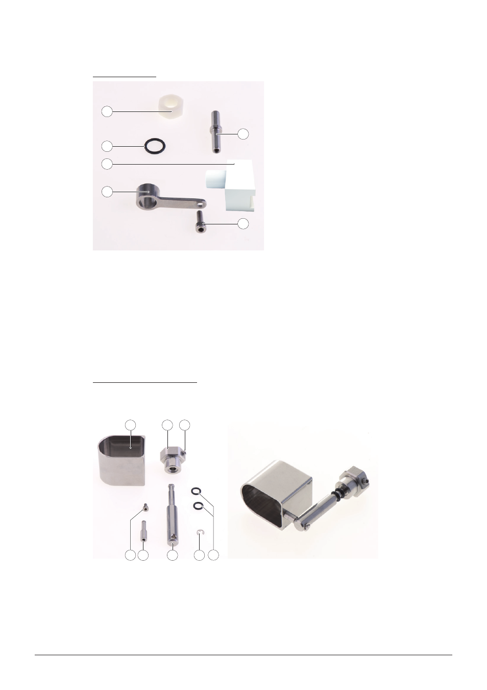
5.4.1.3 Bead bypass system
The bead bypass system is used at the beginning and end of the encapsulation run to eliminate
unwanted beads produced by an unstable stream.
3
1
2
8
4
7
6
5
a Cup
Knob
Screw M5×8
Screw M3×6
Side axis
Main axis
Clip
O-Ring (6.1×1.6)
Figure 5-9: Bead bypass system - exploded view (left), assembled view (right)